Hi guys, been reading through previous posts for the past 2 hours and have figured what I need to do to make a xbox one fight stick from the board of a controller.
The one thing I am stuck on is the triggers, there is a lot of information on this I’ve read but the problem is, a lot of the pictures are dead links and the circuitry look slightly different to my board.
I just want to disable both triggers as they will not be needed as they are currently always on, I suspect the hall sensors have gone…?
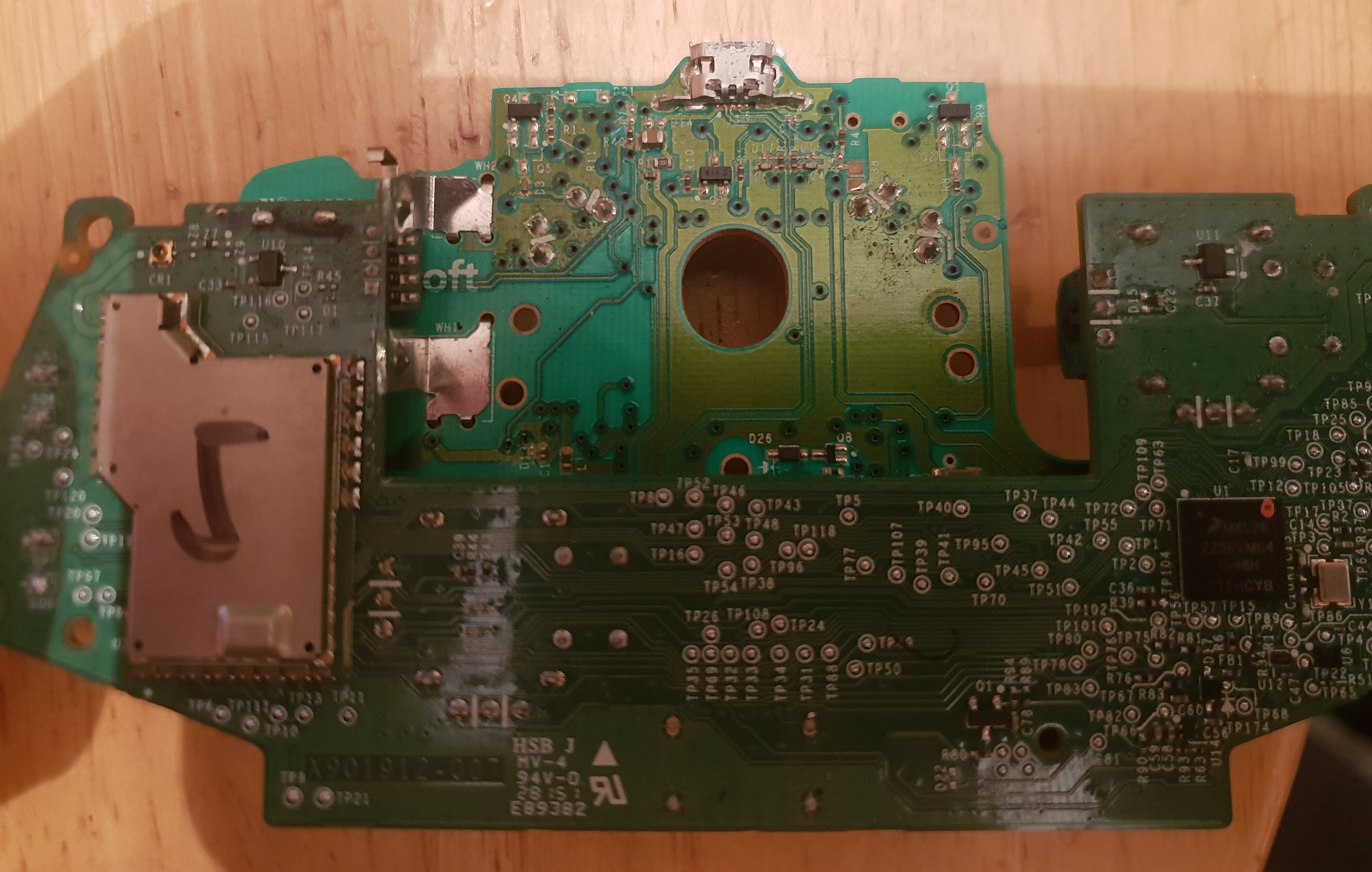
I have attached a photo of my board, any help would be much appreciated.
If memory serves you want a 10k Ohm resistor on each hall (c33/c37 on yours) to a 3.3v source.
Though I don’t believe they should be stuck on in current state, they should be low and pull high with the magnet, were they working normally prior to taking it apart?
Hi, thanks for the reply, yeah I read through your previous posts but we have different boards so felt abit lost.
The triggers were not working before no, but everything else is and I don’t need the triggers for my fightstick as I’ll run off, x,y,a,b,lb,rb,analogue clicks…
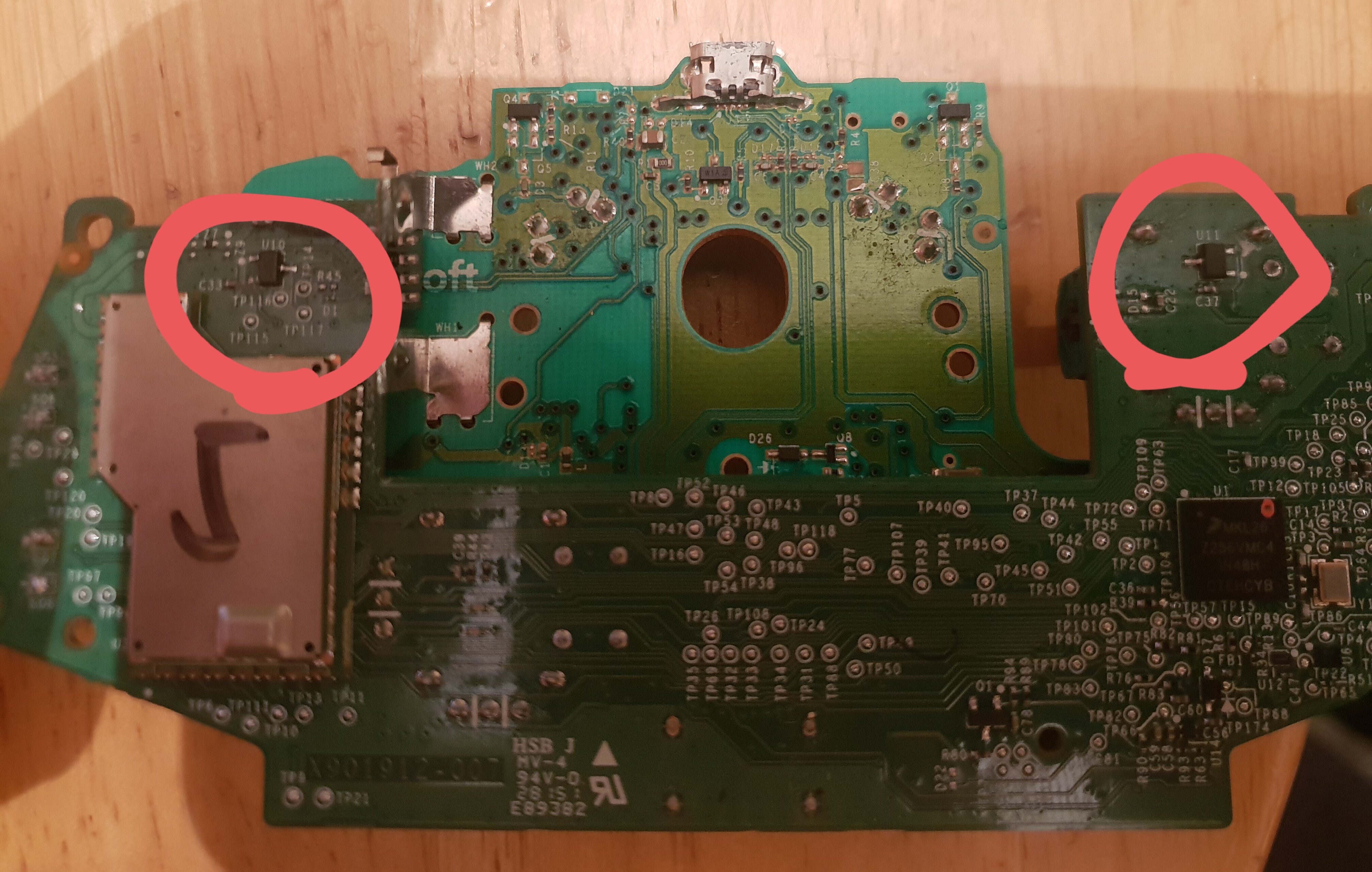
Could you possibly mark on my photo the points I need to fix in the resistor?
10K resistor is good a “safe” value for the older 1697 xbox one controller pcb. If you are good at soldering you can remove the hall effect sensors from the board and put a small 0603 or 0805 resistor between pins 1 and 3 of the hall effect sensor pads. Much cleaner that way.
Also, IIRC, the power for the hall effect sensor was not an always on but switched on once every 8 milliseconds to sample the trigger value then switched off again to save battery power. This is fine because the mcu is only reading the hall effect analog output value while the mcu has the hall effect powered up. The resistor mod I recommended above works well with this power saving scheme.
See response below for the final resistor values for a functional voltage divider you can use to set the R2 and L2 triggers to neutral output values.
Been there, done that! You can actually toss both PS5 ds trigger pcb assemblies and grab the L1/2/3 and R1/2/3 signals right from the main board. No more 8 minute brook timeout.
Okay, thank you for the info, so to disable triggers I’m going to remove hall sensors and put a resistor between voltage in and voltage out. That’s what I understand to be pins 1 and 3.
No idea what caused the triggers to be so glitched out, just happened one day playing PUBG.
Once these are disabled I can use it for my fightstick without obnoxious random inputs from the triggers!!
Okay I’ve tested the voltage in on the hall effect sensors on a functional pad and it 1.3v, the output is at 0.29 when triggers up and 0.2v when trigger is down.
On the board I’m working on both hall sensors are reading 0.01/0.02v on the voltage in! So what I’m going to do is remove both hall sensors and then tap into a V+ line and put resistors in to make a 0.29v line to connect to where to V out was previously…
Can I just leave the old V in board point with nothing connected?
I’ll try to dig out one of my old boards this weekend and post a photo. This is a really old pcb so I’ve since moved on to the slim controller (now also discontinued) and the new xboxx controllers.
The reason you are reading 1.3v rather then ~ 3.2v is because you are reading the average voltage over time with your meter. The power duty cycle for the hall sensor is about 20% and the remainder of the difference due to capacitance in the circuit and performance of your meter. If you put this line on an oscilloscope you will see a short high (on) signal then a longer duration off (low) signal with a slight ramp down between the two point. Nothing to worry about on your good board.
As for your other, make sure you have the two pcb connected properly and not broken any wires or pcb traces. It would be a good idea to double check your work to ensure you have not damaged anything. If the two pcbs (working/non-working) are the same model you should see similar results when connected to a console over usb. Verification is a good place to start as you could have a dead controller.
Looks like you figured it out but 0603 and 0805 are resistor physical package sizes. From Wikipedia :
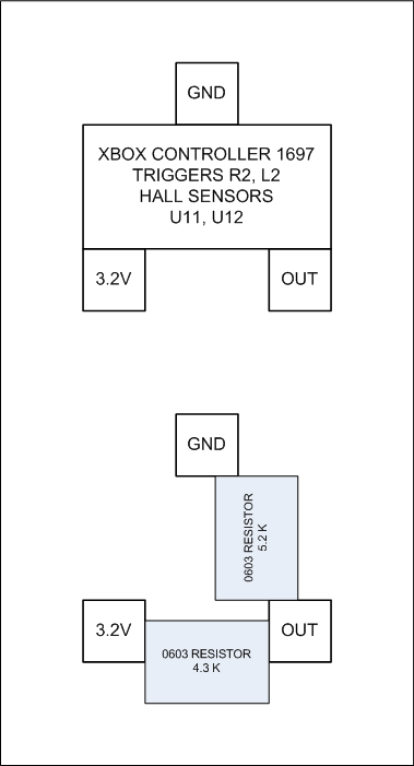
Finally located one of my old modded xbox 1697 controllers in the parts bin along with my notes. I threw it on the scope to verify my notes matched the board hardware and they do. The resistor values you want (approximate) to replace the hall sensors for each trigger are 4.3K between the 3.2v and Output line and a 5.2K between Ground and Output line. This will provide an average voltage on the Output line you can read with your meter of ~ 0.800 volts. (Note: You should also be able to get the same voltage out by installing a 10K potentiometer to be used as a voltage divider in this circuit.)
You can then drive each of the triggers by grounding the respective Output line using a button in your fightstick. Current draw is relatively low so this would do fine even with a battery. but I suspect you will be using this with USB for power anyway.
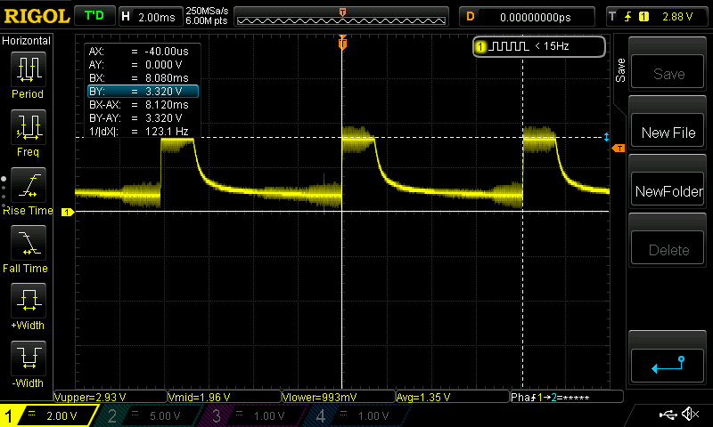
In case anyone is wondering, this a rather less than optimal signal capture of the old xbox 1697 controller powering up a trigger hall effect sensor every ~8ms. Power on (max) voltage is 3.3V but the average voltage is 1.35V. This is why your meter is not reporting the full 3.3V on the hall effect sensor voltage in line.
Thank you ZonbiPanda for the time you’ve taken to help me with your detailed posts!
I’ve been busy the past day or two, hence the late response. I’ve read through your posts and understand your instructions and explanations.
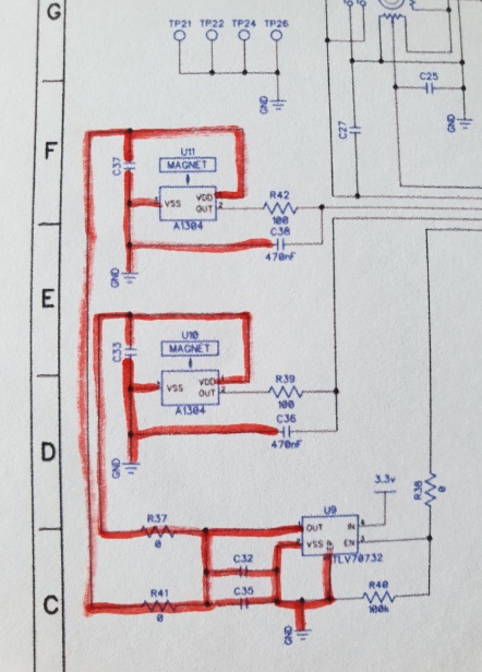
I checked my board against the working board and it seems I have a short within the trigger sensors (U10/U110) and the U9 chip circuitry.
I deduced it could only be one (or 2 lol) of a select few components, including the hall effect sensors (U10/U11) so removed both of them to simplify things by eliminating them as culprits, unfortunately this made no difference so the culprit is either the main brain (MCU?), U9 or one of the very small capacitor/resistors.
I have attached that section of the schematic below, the red line shows everything that is shorted to ground currently. (Granted, some of it should be grounded, obviously)
Would it be okay to just force the correct voltage as ZonbiPanda said above given the state of this short? Can we isolate and emulate?
If you want to stick with the repair path, lift the voltage regulator at U9 and start there as it is your most likely point for a short once the two hall effect sensors are out of the circuit. Try this and report back.
Keep in mind, this is an old ~$10-15 controller now and you can probably pickup a replacement on craigslist cheap. And, since you will be tossing the shell, it only needs to be functional to salvage the parts or make it your new pad hack controller.
Well, I was planning on buying a replacement if I was unable to disable the triggers but to be honest I like fixing things and learning along the way!
Regarding the U9, it is VERY small to me vs. my soldering iron tip/skills, I’m sure I can get it off but I doubt I can get it back on. Will it cause other problems once removed?.. as this pad still functions as a player 2 controller in games where triggers can be disabled.
Based upon your schematics, no, but that is relying on the schematic you found to be accurate and the switched regulator output voltage is not used somewhere else in the circuit. If you pull U9 and it solves your problem then you will still need to either replace U9 and/or jumper power into the voltage divider at each of the hall out / analog input lines. Doing so will be a small constant current drain which is ok when connected to a constant source like USB but not good for battery operation.
Okay guys, I decided to get a new working pad (2nd hand) for my pad hack.
It’s all finished but there is one problem.
It turned on once after not wanting to, and then was fully functional in game until I turned it off, now it is not turning on again, is̶ ̶t̶h̶i̶s̶ ̶s̶o̶m̶e̶t̶h̶i̶n̶g̶ ̶t̶o̶ ̶d̶o̶ ̶w̶i̶t̶h̶ ̶t̶h̶e̶ ̶p̶o̶w̶e̶r̶ ̶b̶u̶t̶t̶o̶n̶ ̶n̶e̶e̶d̶e̶d̶ ̶a̶ ̶c̶e̶r̶t̶a̶i̶n̶ ̶g̶a̶u̶g̶e̶ ̶o̶f̶ ̶w̶i̶r̶e̶ ̶o̶r̶ ̶s̶o̶m̶e̶t̶h̶i̶n̶g̶?̶
It’s got me really puzzled.
edit
I’ve checked everywhere for shorts and tried a different power supply, all is fine, I’m thinking I’ve bridged something, I removed the power button connection and glue (X button) and its clear of shorts. It works just fine though USB.
Update after testing, when the batteries are put in the pads light comes on (strange) and during this window if you hold the power button it turns on… other than that it does not.