I seem to recall batteries were required for this to function but that may be the ps4/5 controller I’m remembering. Best course of action is to disconnect all of the wires soldered to the pads and isolate them and retest. I see screw terminals in the image so that should not be an issue.
Make sure your two pcbs are pressed firmly together and that the pcb to pcb headers are not crack. There is a similar led flash error when the two boards are not communicating properly.
Did you test the new controller before disassembling for the mod???
1 Like
Yeah the pad was fully functional 100% before the mod, I did what you said and now completely out the blue the right analogue stick is hard drifting to the left, I swear I was so careful to do everything right and now all these random inexplicable problems…are these PCBs just mega sensitive or what?
Got a meter? Remove power from your board. Measure resistance on each 3 pin joystick potentiometer between the outside pins and then each outside pin to the center pin. One outside pin is VDD (switched), the other GND. The center pin is stick analog voltage out. You should see a roughly equal resistance between each outside pin and the center pin when the joystick is centered. If not, you have a short somewhere between center pin and VDD or center pin and GND.
On a side note, when I tap the pads on a gamepad I use a very thin solid core AWG 30 wire. Experience has taught me that any heavier wire is more likely to rip the pads off the pcb with leverage than not. The smaller gauge wire bends and flexes more to preserve the pads. Flex such a small wire too much and it will break but at least your pcb is less likely to be damaged.
2 Likes
Okay, thanks again ZonbiPanda!
I’ve tested as you said I’m getting low resistance values even when I’ve taken out the wiper.
All the other outer-inner resistance are at 4k, the buggy one is 2k and 73! (Vin to v out and v out to ground respectively)
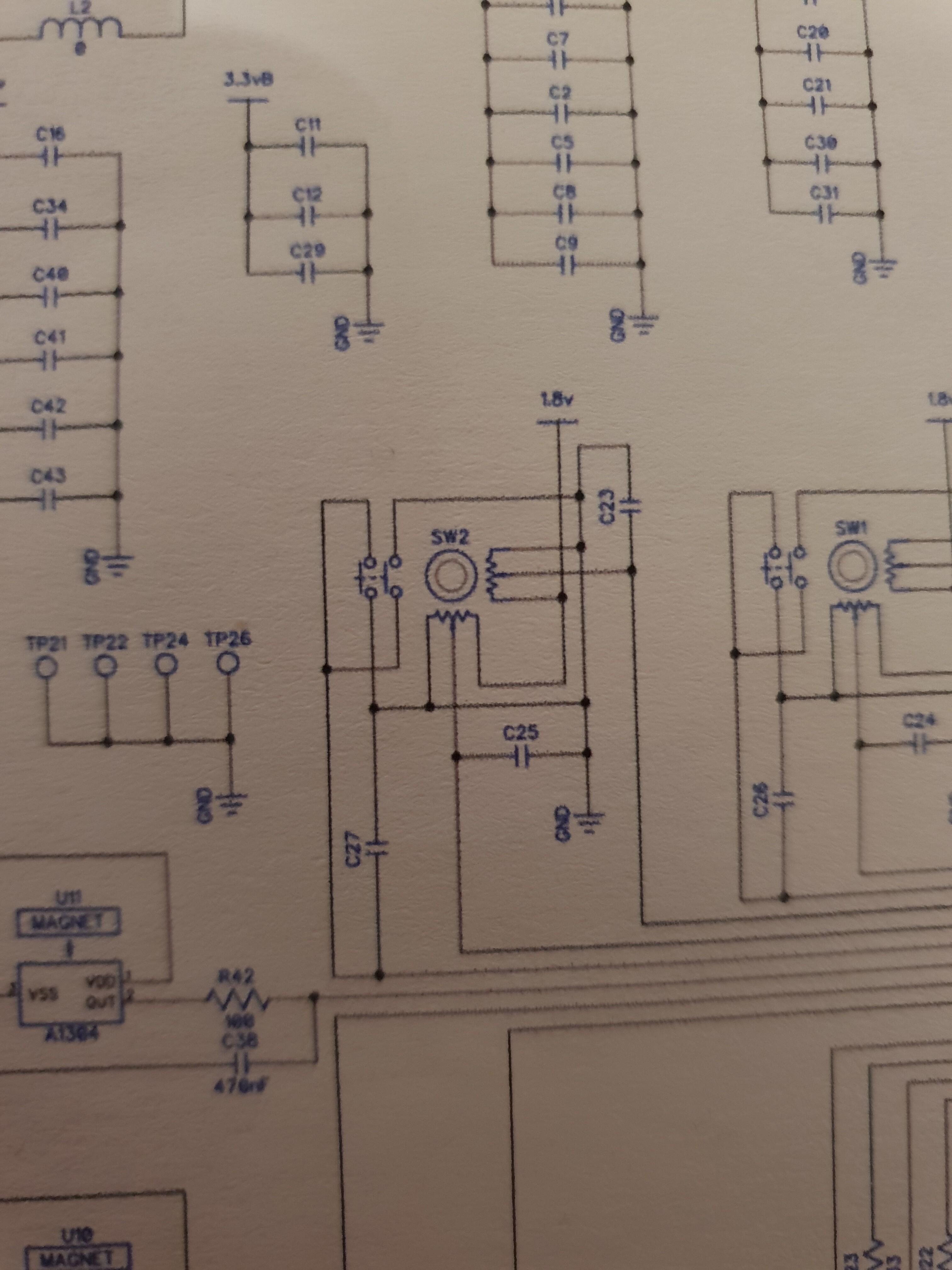
I’m suspecting the c25 capacitor as it’s the only thing in between the middle pin and ground (possibly c27???) either that or main chip problems… why do I get all the freak problems?
Never smooth sailing even when I’m careful!!!
Ok so I’ve tried this pad hack and it work for a while with just a 100ohm resistor for the triggers. But it has stopped working. So I figured maybe we can bypass the Hall effects sensor altogether and instead use a mechanical switch and use that for the pad hack. Well turns out someone has a video bypassing the Hall effects sensor with a button switch. This seems to be the easiest fix for pad hacking trigger issues. I plan is doing this and it’s really simple. Check it out! https://youtu.be/v9LgcxOQFlw
Yup, clearly between VOut and Ground on that potentiometer. Congrats on tracking that down with the meter. You will use this new skill for years to come.
It’s unlikely that a ceramic capacitor would go bad but it is possible. When they do, these usually crack due to shock, compression or large temperature variations and typically create an open not a short. Feel free to lift the suspect capacitor off the pcb if you want test out this theory.
It is more likely that you created a solder bridge somewhere while doing the rework. If not, you may have done some damage with the soldering iron, possibly lifting a trace or damaging another near by component - even on the opposite side of the pcb. I suggest you take a step back and review the pcb with a magnification lens and see if you can spot anything.
Did we cover what type of soldering iron you are using? If it has an adjustable temperature setting always use the lowest setting that is sufficient to perform the necessary work!
1 Like
This only works when the magnet is still influencing the hall effect sensor. I.e., Adding a second trigger while retaining the original trigger.
In @bagootimbre 's case, he has removed the shell and triggers with the magnets (based on his photos). We are discussing removing the hall effect sensor and biasing it slightly with a resistor based voltage divider to provide the controller with what it expects as a neutral position on the trigger. Once that’s in play you could ground the output of the voltage divider to “activate” the trigger. However, @bagootimbre 's fight stick is not utilizing the triggers so they just need to be neutralized and removed from the equation.
@Greengummybears good for you using the 100 ohm resistor to provide some protection to the circuit. I would recommend pushing that value as high as you can go to reliably trigger the input. Try starting with a 1K and go up or down from there. It is always a good idea to reduce current flow to an absolute minimum to accomplish any task while enhancing circuit protection in the process.
As for troubleshooting your issue, I suggest a good visual inspection of the pcb and not just the areas where you performed rework. If you don’t spot anything, try undoing your modification and see if the controller behavior reverts to normal expected behavior. Beyond that you will need some tools like a good meter or better yet, an oscilloscope to troubleshoot things quickly.
1 Like
I’ll take a step back like you said and really inspect things, as there is still glue on some parts of the board (I didn’t want to undo everything it took ages lol).
Nothing looks bridged and these PCBs are just a layer on top and on the bottom right? (2 layer?)
I’m using this iron, please don’t scald me too much, this was meant to be a budget DIY project but I’ve found myself drawn into electronics diagnosis now!
I would need to pull a pcb and look but at a minimum it’s 2 layer, possibly 4. It’s been a while since I’ve worked on the old controller. Everything went to the 2018 S and then the latest 2020 models.
Your soldering iron is fine for what you are trying to accomplish. Next upgrade I would recommend a 60W unit but 40W is good enough for this project and probably better for the smaller parts. I am fortunate enough to have a full JBC soldering station with all the bells and whistles. I use it for business so I can justify the cost and, honestly, could never go back to my (real Japanese Hakko not a Chinese clone) after using the JBC rework station. Heh, my last JBC replaceable soldering tip cost 5 times what your entire soldering pencil cost. It’s expensive but worth it! 
Keep looking, i’m sure you will find your short. Remember to retest for that short as you remove various pieces of your mod. Based on your soldering iron voltage you do not appear to be local so I can’t offer more hands on assistance or a hardware swap being 8 time zones away.