@Vicko Did Infil ever give you a peek at his beta Atrox setup at NCR?
Nope! He said “later” and later never came 
Yeah that’s the Sground, or the copper sheild wire that runs through the cable. Solder that as well for less EMI and static electricity buildup.

Here is my Razer Atrox (XBox 360 model) set up with the Brook Universal Fight Board PCB. Pics & write-up below! I will also include a full list of parts used @ the end of this post, as well as where I got them from.
I’d like to give a huge shoutout to @Dubon & @Vicko - I don’t think I would’ve been able to pull this off without their help!


Gutting the stick:
First thing of course was to remove the stock PCB. Very straight forward and easy, just unscrew the 4 screws holding it in place, and unplug everything from the Circuit Board. Remove all of the quick disconnects (QDC) from the buttons. If any of the QDCs are stuck, I found the best way to get it off was to stick a flathead screw driver (the one that comes with the stick works fine) at the very top of the QDC, and to push down gently - this seems to give it enough of a push to come off smoothly.
One thing you’ll notice is that 2 cables run from the PCB around the right side of the stick. This is for the audio jack (not supported by the Brook PCB) & the front LED. The adapter with 2 cables is for the LED, and the adapter with 4 cables is for audio. To free the cable, you have to unscrew the stick holder, as well as the angled edge of the stick. (Front right part with 3 screws). You’ll need a long screw driver to access these - the one that comes with the stick is not long enough.
I cut the audio jack cables clean off as I have no use for it - never used it before anyways. Cut the adapter off the end of the wires for the LED - you will have to solder these to the board to get the LED working (details below). After freeing the cables from the right side, I removed the cable holder to route the cable through the left side, where I have my PCB.
Making room for the Neutrik USB adapter:
Technically you could get away without doing this, but if you’re going for the mod, you might as well do it right IMO. The Neutrik adapter just lets you plug/unplug your cable externally, rather than having to feed it through the hole in the stick, and directly into your PCB. In the event that something caught the cable, it’s of course much better to have it tugging on an adapter than directly on your PCB!
The stock cable hole isn’t nearly large enough. I used a dremel to open it up, but I imagine a drill with the right bit size would work just as well. I just took off a little bit slowly, checked if the adapter fit yet, and repeated until it fit. Now unfortunately I’m not the best with the dremel, and didn’t make a perfect hole. I was pretty choked up about this at first, until I found the rubber backing you can get for it. It covered it perfectly! I highly recommend ordering one alongside your Neutrik adapter. It looks good, even if you didn’t make a mistake. See the pics below - if you look closely you can see the green rubber from the inside.
The dremel also slipped a couple times and marked up the inside, but after covering it with black sharpie, you can’t notice it unless you’re looking for it.
Once I had the adapter hole made, I stuck the adapter in, marked where the 2 screw holes were, and drilled 2 more small holes. One last note about the adapter - the USB B portion is facing inside the stick when you receive it, but it is fully reversible. Unscrew the metal plate on the inside, and you can easily flip it around, so that USB-A is on the inside (which is what you need).
I used a vacuum to suck up all of the mess that the drilling did, which worked perfectly.


Getting Started
Unfortunately the screw holes in the PCB don’t align perfectly with the Atrox, so to screw it in to the hex floor, you will have to put it at a bit of an angle (not a big deal of course.) You will only be able to fit 2 screws in, in opposite corners, but that’s all you’ll need.
Setting up the core functionality (buttons & stick) is very straight forward and hassle-free, thanks to the screw terminals in the Brook PCB. Hook up all of your wires to the buttons (I personally think it’s best to start with the daisy chain), and the 5 wire connector to the stick. A lot of the QDCs seemed to be too tight to properly fit on, so I had to open them up a little bit using a flat head screw driver. After I put them on the first time, they stuck very tight as well - I had to use the screw driver plying method I mentioned earlier. After I used the screw driver once, I had no problems taking them off/putting them back on after.
Once you have all the wires hooked up, cut them down to size and strip the ends. You want to keep a little bit of slack, but not too much.
You only need a very small amount of wiring stripped. I would just strip it, twist the end, stick it into the screw terminal, and see how much bare wire was sticking out, and cut down accordingly. Make sure you keep the ends of the wires twisted, otherwise you’ll have a rough time trying to stick them into the screw terminals. If you’re not familiar with screw terminals… all you have to do is stick the stripped wire in, and twist it down with a screw driver. Very easy.
Stick the daisy chain into any ground terminal (I used the one beside the Playstation/Xbox button), and each button into their corresponding screw terminal. If you have the stick in the same position as in the picture, connect Red = Down, Orange = Up, Yellow = Left and Green = Right.
Once you’ve done this, you’ll want to connect your PCB to your Neutrik adapter, the adapter to a computer or console, & test everything inside a game. Once you’re satisfied that all buttons are working, it’s time to move on to the more complicated stuff!
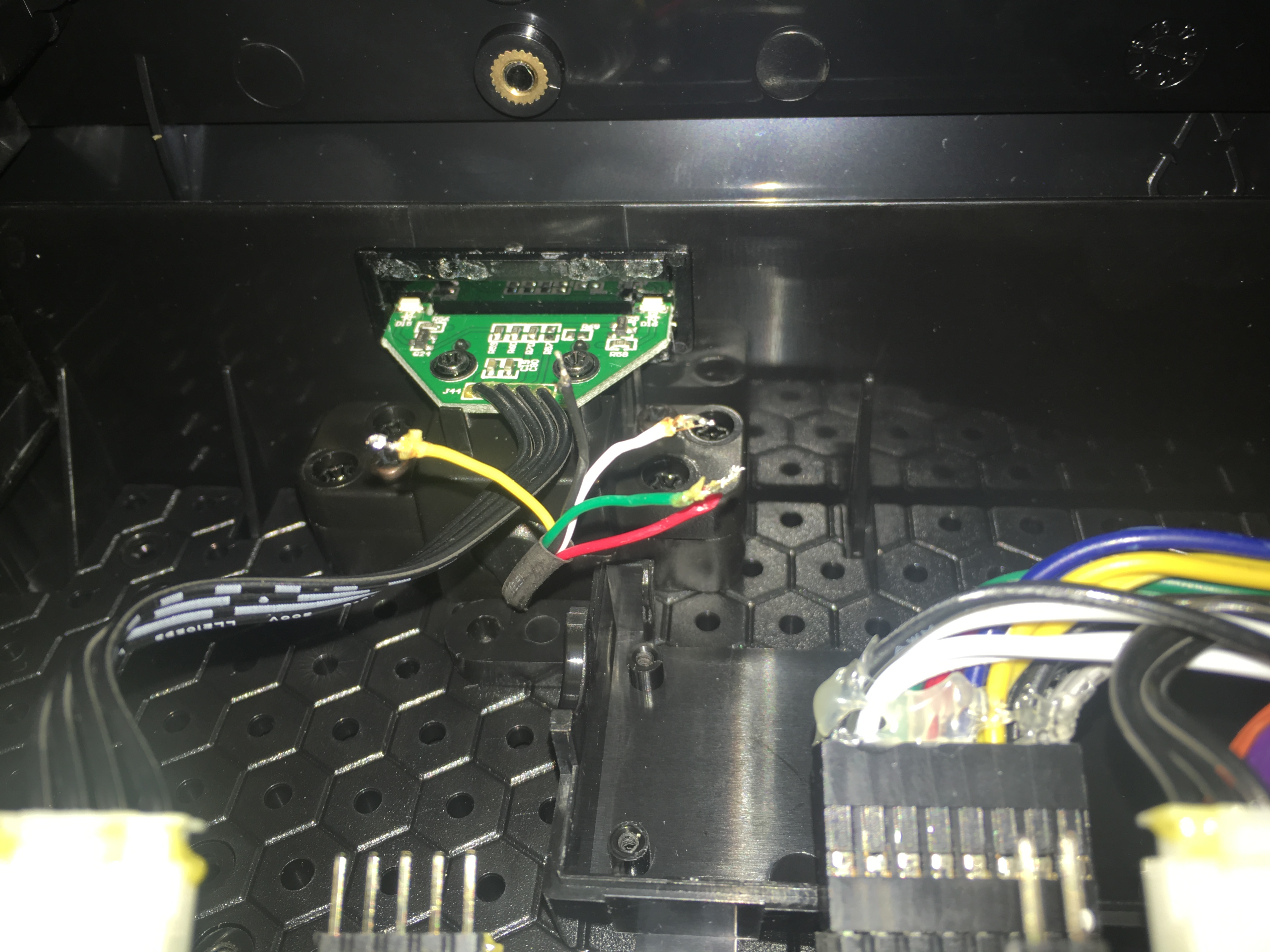
Working with the Turbo panel
This is where things start to get tricky. @Dubon kindly provided the schematics for the board, but I still ran into a few issues; mainly that the main way to access the Turbo panel is from the bottom, but the schematics show it from the top. See the full schematics below, as well as an easy-to-follow diagram I made below, so you don’t make the same mistake.

As a result, I pulled out the wrong cables from the adapters (as I was pulling out all cables from the adapters that I didn’t need). Fast forward 2 frustrating days, @Dubon realized & pointed out this problem, and I was able to fix it up. Don’t panic if you remove the incorrect wires, you can just stick them back in as long as they are still connected to the crimping. And there will be more than enough excess wires if you manage to break some crimped connections as well.
To pull out wires, first cut off the adapter on the PCB end. The cleanest way to pull the wires out is to (somewhat gently) lift the black plastic holding the cable in from the outside with a very small screwdriver. Flip the adapter upside down while you have it pried open, and it will usually slide out - if not, just gently pull it. If you don’t have anything small enough to do this, you can also just pull it out with force, although sometimes the wire crimping will get stuck in the adapter, leaving you with one less wire you can put back in if you make a mistake. If the crimping gets stuck, the only way I’ve found to get it out was to pry open the plastic from the outside.
There are 9 wires total - 8 remain connected to the 16-pin adapter, and only 1 on the 10-pin adapter. Take note of which pattern is on which wire, write it down, plug the adapters back in, and screw the Turbo panel back into the top of the stick.
Testing
The first thing I want to say about this, is that when you plug your stick into the computer, it defaults to XB1 mode, which lights up all player indicator lights. This confused the hell out of me for the longest time. To force it into XB360 mode, first, make sure you have the latest firmware update - then, hold down the 3P button while plugging your stick into the computer. This way, only the appropriate P1/P2/etc light will come on. If you’re testing on PC and have 3 other controllers, I recommend this. However the XB1 mode can be useful to make sure your lights are working if you don’t have other controllers to use to force your controller into being P2/3/4.
Note: To update the firmware, you will need to press Select & the PS/XBox button (aka Home button). If you need to update the firmware before you’ve connected the home button on the turbo panel, take your Start cable & move it into the Home button screw terminal.
Anyways, to test that a connection is working before you solder it, simply strip the end of a wire, and stick it in the appropriate hole.
VCC and Ground from the turbo panel can be connected directly to the screw terminals of the PCB (I highly recommend using it.) Note that Ground and VCC will have to be connected to the rest of the turbo panel functionality to work. The home button will also have to connect directly to the screw terminal.
If any given player indicator light doesn’t seem to be working, use an extra wire to connect that indicator directly to ground (eg. P1 to ground). If the light is functional, the light will turn on.
Soldering
I find it best to do 1 wire at a time, and test after each time to make sure it’s working, and that I hooked up the proper cable. To separate the solder between the player indicator holes, I had a friend hold a business card in between the holes while I soldered (I have a garbage bulky iron which made things difficult).
For the Razer logo LED, you will need to connect the cables to ground and VCC on the board (do not use the screw terminals!) If it doesn’t light up, switch the cables around and you should be good. I used the Turbo VCC & Ground.
For the LS/RS/DP switch, there are only 2 cables, but 4 holes. Use the far outside holes.


As you can see here, the player indicator and front LED work beautifully.

Gate Holder & Stick Holder
The gate holder was 3D printed - you can grab one here. I designed this about a year ago and it is made to fit the hex floor perfectly.
It’s not a perfect fit for the gate though, and neither is the stick holder for the JLF link - it bounces back and forth which I always found annoying. I super glued some foam I got from the dollar store together, and hot glue gunned it to the inside of the gate holder and stick holder.
Final notes - I put some labels from a label maker over the default XB360 layout, which makes it much easier to quickly see what’s going where. I got the Blanka & Guile stickers a while ago, and I think they were from focusattack.com, but I couldn’t find them on the site now. I believe they were being sold as screen cleaners, though they make for excellent stickers. (Sticker screen cleaner hybrid? Never used it to clean a screen, and if it’s actually for that I’m not sure why they’d have sticky backs… still confuses me lol).
I screwed in the stick holder and PCB using #4 machine screws.
The cable sleeving I got from here and it can be put on after all the cabling is done.
Thanks for reading & have fun modding!
Parts list:
Razer Atrox XBox 360 Model (No longer in production, Razer currently only makes the XB1 model).
Brooks Universal Fighting Board
Neutrik USB Adapter
Neutrik Adapter Cover
16 Wires with QDCs (for buttons) (only actually need 10, but I went with the pack anyways)
10 connection daisy chain for ground
5-Pin wiring harness (for the stick)
18 Inch USB Cable (for going from PCB to USB Adapter)
10 ft. USB Cable
The Link Quick Release JLF Shaft
#4 Machine Screws (various lengths)
Cable Sleeving
3D Printer Gate Holder
excellent write up
Thanks! 
i tought you drilled the hole for an extra 24mm button. Did you consider mapping tp button to one of the turbobuttons? thats what im planning to do once my ps3/ps4 board gets here
Great mod, hope the case doesn’t fail on you.
My initial plan was to do that for the home button until I realized I could get the home button on the turbo panel working. I might do that in the future but I never use turbo so I don’t have plans on doing it any time soon
Does that happen?
Anyone else have issues with this stick directional’s getting stuck until you press a button?
So I have one of these coming from Amazon and I was seeing is it possible to use the existing the preexisting usb with the brook universal board? Like I know it has solder points but wasn’t sure if the usb already could be done that way.
Yes, but you might have a hard time soldering since the wires are so short. I added about 2.5cm of 22awg stranded wire to each usb wire to make it a bit easier to work with. Make sure to heat shrink over your solder when doing this so the wires don’t touch.
Oh another question is does anyonek now if seimitsu parts work with it? I know the te2 has issues with the thickness of the buttons or something like that
Yes. The Hanayo Atrox in my signature is full-Seimitsu. MAke sure the joystick you’re using has the MS mounting plate.
Is there a schematic for the stock board for the 360 atrox?
uh, its been posted on this page in this thread. Scroll up
Yes it does.