I’ve got some picks form the PCB, sorry that I couldn’t disconnect some of the plugs in the PCB, I did try but I might damage it in process 
If you are replacing the main PCB with a PS360+, then why even worry about not damaging the original Razer PCB?
If a connector with some wire do not come loose, then snip the wires.
Oh sorry then, maybe I asked the wrong question 
What I want is to keep the Home + player leds indicators form the Atrox, how do I hook them to the PS360+ ?
Did you read the PDF I pointed out.
It shows how to hook up the LEDs on the PS360+ side of the board.
As for the guide PCB I can’t tell you but this post will give you some insight, hope you have a multimeter
The Razer Arcade Stick Thread!
Got it, for the LED’s thing 
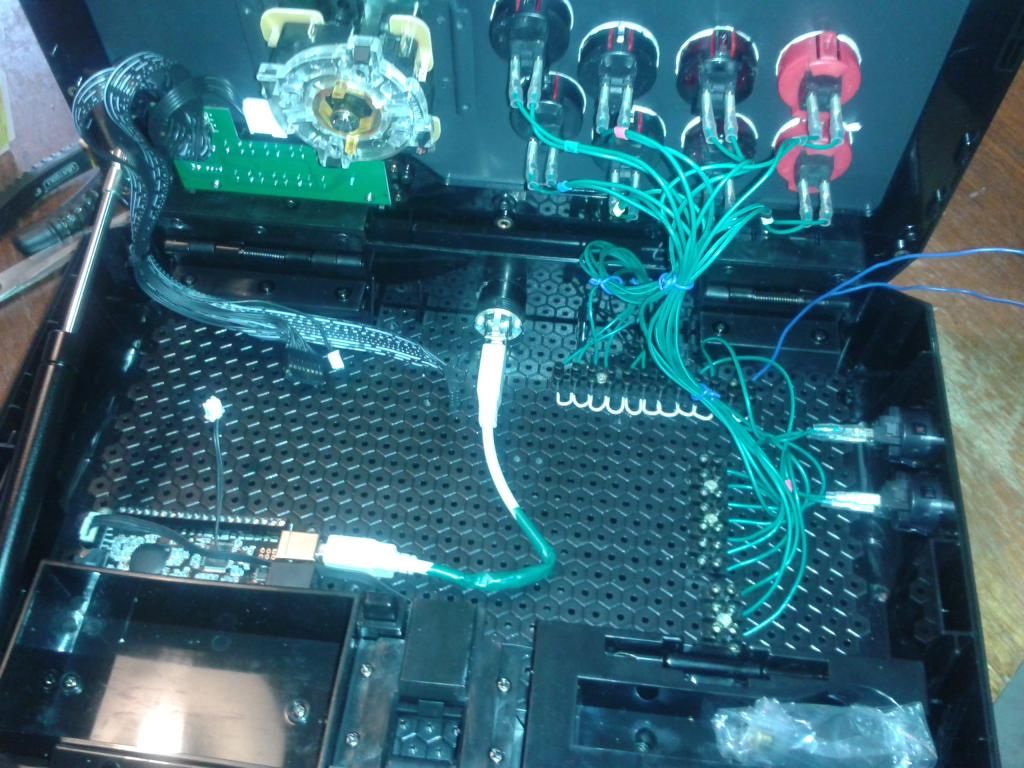
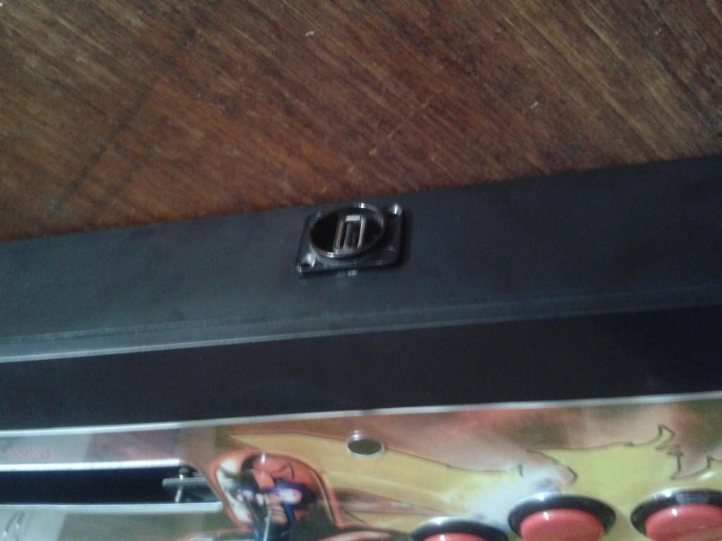
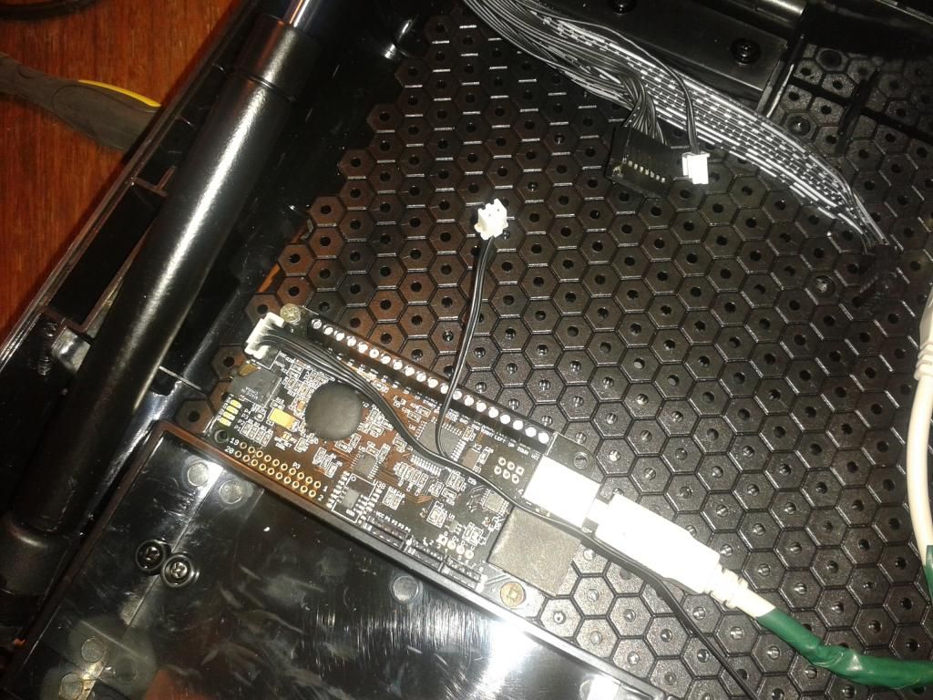
I took out the original PCB and got a PS360+ there. I also merged all of the buttons + Back + Start ground cables, plus drilled a hole for a USB Neutrik connector.
I took a couple of pics from what I’ve done so far:
Spoiler
http://i824.photobucket.com/albums/zz167/galaxiqqcl/20140311_161503_zpsdc6d3798.jpg
http://i824.photobucket.com/albums/zz167/galaxiqqcl/20140311_170606_zps878e823f.jpg
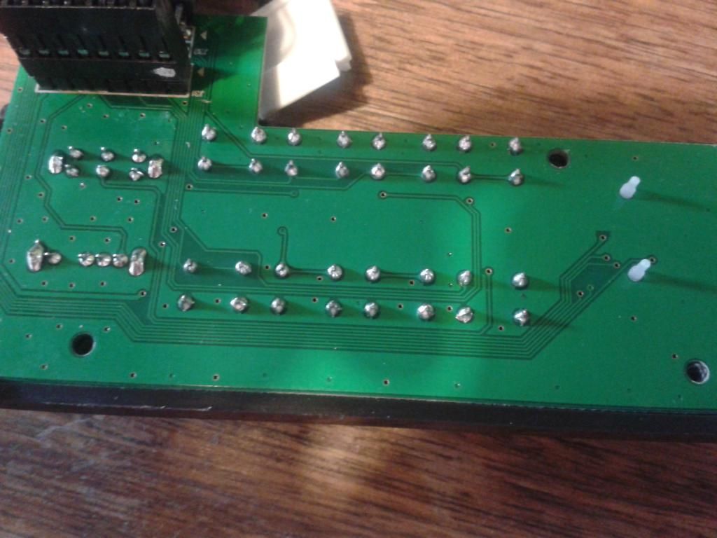
Now I have to do the home + leds thing from the Turbo pannel PCB, here’re some pics:
Spoiler
http://i824.photobucket.com/albums/zz167/galaxiqqcl/20140311_170651_zps821f5247.jpg
http://i824.photobucket.com/albums/zz167/galaxiqqcl/20140311_163626_zpse6a6d4a9.jpg
Any help? I’m pretty new at this like I said
Also, where do i put this small cable which comes from the frontal part of the case? I assume it’s the light from the Razer logo when it gets On. It’s just next to the 360 headset cable.
That small 2 pin cable are the LED in front. One wire is ground and the other needs to go to VCC if you want that LED to work.
I got no idea at the moment which wire is which.
As for where to connect for your guide button, you need a multimeter and test out which wire is ground and which is your guide signal.
Got the frontal LED working  Thanks!
I don’t have a multimeter Can this image help me on this?
I tried wiring “Gu”, “VCC” and “GND” according to those points, but nothing happens.
EDIT: Just after connecting the frontal LED, after several minutes, I started to smell some smoke LOL, so I disconnected the Neutrik ASAP and after that disconnected both VCC and Ground.
Here is where I connected the LED wires
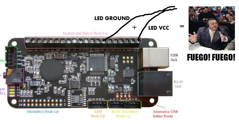
No luck with the Home button according to the Atrox PCB image, I connected the Guide, Ground and VCC cables.
I don’t think this has been answered yet, but I can confirm that Sanwa OBSF-30RG buttons fit perfectly into the Atrox, with absolutely no issues whatsoever. I think there was some concern about there not being enough clearance. There is enough. Now if only Focus Attack carried these buttons.
Regarding putting a PS360+ in this stick, will I need to get screw terminals or will I be fine without them. I personally haven’t looked at the PCB itself in person to know.
The PCB already has them
Alright thanks, that is what I assumed, but like I said I hadn’t checked to confirm.
Finally got around to starting this. If I don’t care about the Atrox PCB, is all I have to is cut the wires and connect them to the PS360+. I don’t care about the using guide button either, so I don’t have to worry about that. Sorry for asking, I just don’t have much experience working with the PCBs of arcade sticks.
You will need 1 wire from each button attached to the corresponding terminal, and each button needs to be grounded. Best way to deal with the ground wires would be to make or buy a ground daisy chain, as you don’t want to be stuffing 11 ground wires (1 for the joystick) into the available terminals- you could rig it up with wire nuts, but it’s so much better to just buy one of these: http://www.focusattack.com/10-connection-110-ground-daisy-chain-wire/
You will need to separate the wires of your joystick harness a bit, hook up each directional wire to the corresponding terminal, then connect the ground wire to a PS360 ground terminal. This is what you’ll need if your existing 5 pin harness isn’t long enough: http://www.focusattack.com/5-pin-wiring-harness/
You’ll also need a short USB (or RJ45) cable and a pass through connector for whichever connection method you’re going to use. Technically, you could just run a long cable straight out of the PS360 through the case, but this is pretty much guaranteed to give you grief later on.
Thank you President Camacho. The ground wires were the only thing that I was worried about as I know I need a pass through as I am going to use a RJ45 cable.
You ever figure out how to avoid the fire hazard? I’m thinking of putting a PS360+ in when PS4 support drops and I have grown attached to the cycling led.
hey guys
I’ll try a cerberus on my Atrox, how’s is it working for you? any problems so far?
and is there a tutorial or something? I guess the assembled one does not fit.
You had too large of a current, you need to put a resistor on the line before the LED
What’s the consensus on using a ps360+ in one of these?
In a Razer stick? Go for it.
Seems easy enough. I’d like to be able to use the led lights without blowing the house down though. And I’d prefer not to have to drill for a neutrik so is it possible to use the stock pass through without soldering?
You mentioned a resistor for the leds. What kind would you say would work best?