The only reason why I’m posting here is because Tim monitors it, Stanley called and couldn’t reach Tim 3 times in 3 weeks. If it’s tough to get to Tim by phone, maybe I can through ShoRyuKen.
I think I’m running into the PS2/PS1 issue you discussed earlier in the thread. I have two sticks with MC Cthulhus in them, and having oddities in that only one of them will work most of the time when both are plugged in. If I’m plugging or unplugging, it’s typically the last plugged in.
sometimes works when no memory card is plugged in, or if I boot to the PS1 white screen and then quickly reset
it’s a PSone fwiw
don’t know if it’s like a non standard voltage or what
if I only have one plugged in on either side, it always works fine. if a controller in on port and a stick in the other, also fine
Anybody ever run into this and if so, know a workaround? Doesn’t seem like my board is bad, because both are behaving the same way. Thanks in adv for any help
I got a message formPara=dise arcade Shop. Tim, who monitor this SRK thread, no longer works for Paradise, so it will be a while before you get web help.
Also the phone number to Tim’s Paradiser numbr is shut down and Paradsie’s main phone number has a prerecorded message with no chance to leave a message.
Me and Stan are trying to get some help.
Also does anyone know how to send an email to Payapl from a mail program, not their weebsite something in the form of "somethng@paypal.com".
Apparently none of Paypal’s text chat tech can seem to understand me.
If someone can, this can help solve a spat between me ands Paradise.
Has anyone ever successfully used the MC Cthulhu SNES cable on Donkey Kong Country? My MC Cthulhu only seems to work on certain games, and DKC is not one of them. My NES controller only works sporadically as well.
anybody know where to get a programmable firmware file for the PIC? The PIC on one of my cthulhu’s seems to have gone bad.
Would be nice if the file were released, since it seems the cthulhu’s are no longer going to be produced.
This would greatly help a lot of members over at Arcade-Projects for the Jammafier device. We’ve been trying to get Arcade Paradise to restock the chips for the MC Cthulhu’s, but they’ve yet to do so.
I believe there are at least 20 people looking for it over there.
Here the firmware
1 Like
Unfortunately, you cant just program a pic with the firmware file. I dont claim to know all the workings, but the program tool only writes to a portion of the pic. If a pic fails or corrupts, there’s no way to replace it…at least that i’m aware of. Would love to be educated otherwise if a solution exists.
2 Likes
FYI: paradise arcade has restocked the MC Cthulhu PIC, for anyone looking for a replacement.
1 Like
I am not too sure, but finding the file is better than nothing.
I also saved it onto my own computer for later archiving
I just got a Toodles Cthulhu Multi-Console PCB brand new from Paradise Arcade. Do I need to update it? If so, how do I do it, and where is the software that I need to get it?
No.
I want to say that the Paradise arcade version of the Toodles Cthulhu Multi-Console PCB is using the last firmware Toodles made for the MC so it needs no firmware updates. Only reasons I see to reflash the Cthulhu is if you want to switch between the 10 ms and 1ms delay versions of the Firmware.
My previous Wayback machine post has the last firmware version, it also has a executable for updating. You will need Microsoft’s .Net frame work runtime installed to run the updater.
What are the advantages and disadvantages of the 10ms and 1ms delay versions of the software? Also, do you have a guide on how to change from 10ms to 1ms?
One takes 10ms (miliseconds) to send a signal to the console and one takes 1ms. The 10ms is more “stable” but many fighting game players prefer the 1ms timing.
No. Everything on the link, in the zip file there a txt file read me.
I don’t have any other info for you.
What’s the best way to hook up a Brook UFB to a Toodles Cthulhu? I happen to have 2 Cthulhu PCBs, and plan to mod my friend’s MAS stick.
Has anyone here used this with the Brook PS3/PS4 adapter to Switch? Or with any Brook adapter?
It mostly works for me, but the buttons that would correspond to R2 and L2 on the DualShock 3 are not recognized by the Switch. I was just wondering if anyone else had any experience or insight to this issue.
Thank you.
I’m thinking of trying to develop a no color method of attaching the Toodles Cthulhu PCB to external devices via RJ-45 modification. Please note, that this is ONLY RJ-45 modification and has nothing else to do with Cthulhu installation. This “possibly” nullifies the need to know any of the following accurate [and yes this is accurate BTW…] information related to the color scheme for soldering.
Only solder to the positions nearest to the USB B Female port.
-No matter what method used for this, it is always soldered to these places, and this part needs to be known irrespective to all else.
G= WHITE Ethernet wire with YELLOW or ORANGE STRIPE
-lighting and dye color plays a part in the color of the stripe
A= YELLOW or ORANGE [solid/no stripe]
-See previous
B= WHITE wire with the GREEN STRIPE
-Be careful, this can be confused easily with the white one with the blue stripe.
C= BLUE wire [solid/no stripe]
D= WHITE wire with the BLUE STRIPE
-Be careful as this is easily confused with B [White with green]
E= GREEN wire [solid/no stripe]
F= WHITE wire with the BROWN STRIPE
U= BROWN Wire [solid/no stripe]
This is the method I used to attach an RJ-45 male cable directly to my SECOND Cthulhu board. The male end [with a boot attached] was attached to a female female coupler, and the female female coupler to whatever console cable I want. This was done correctly. So what happened to the first one? Read on to find out.
For this strategy to work, I would need something like this…
In case this is removed, here’s a picture or 2…
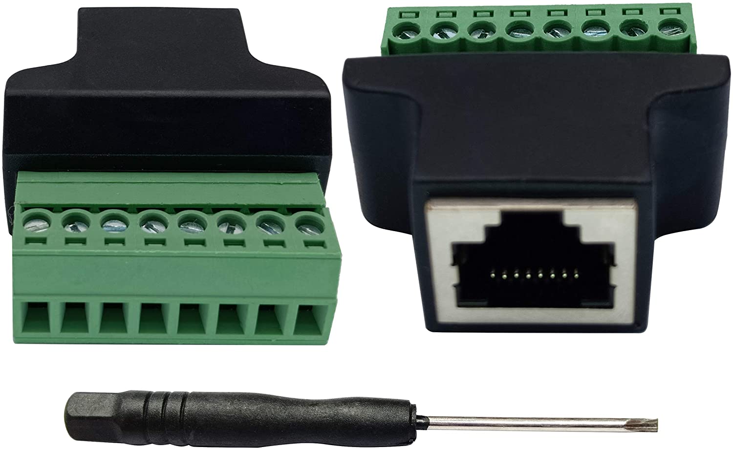

I believe these are sold in pairs.
==============================================================================
WARNING: EVERYTHING FROM HERE TO “EXPERIMENT ENDS” IS EXPERIMENTAL
-Don’t trust it.
The idea is to first attach straight 1.5" wires between the 2 terminals and then attach them to a cable tester to find out where each goes to. I’m assuming that they are in the proper order. If they are, then I plan to solder on the 1.5-2 inch wires [all EXACTLY the same length…] into the Cthulhu. Ensuring that the wires are in order and uncrossed, it will ensure that there are no errors. With the USB port on the Cthulhu pointing down, and the rj-45 port facing away from me, I plan to go in number line [left to right aka left =1, right =8] order…
G= 1
A= 2
B= 3
C= 4
D= 5
E= 6
F= 7
U= 8
If this works, errors with soldering the wrong colored wire onto a Cthulhu during an RJ-45 mod will be a thing of the past. In the event that it does happen, you simply correct it at the screw terminal. And it would be obvious as you’d see wires crossed. It should be unnecessary for any of the wires to ever be crossed if this is engineered correctly.
EXPERIMENT ENDS
=============================================================================
I accidentally destroyed by improper soldering the first Cthulhu. [I had 2, the second one was done properly via colored wire installation method in part 1…], I can save others the frustration of accidentally soldering the wrong wire to the wrong point, having to detach and re-solder the wire, and risking destroying a solder point [like I did].
This will allow me to experiment and possibly fix my damaged Cthulhu.
Wish me luck. Also, feel free to test this method and let me know how it works.
Perhaps this thread might be a better place to post this. Maybe this will help?
I updated the RJ-45 Thread
on making console cables and cleaned up the pinout charts. Instead of reformatting using the SRK forum, I just made a PDF.
Feel free to download this for your personal use.
https://mega.nz/file/FAt2iYSS#gnScCNKxgOSP-subKhSRLDjkmXEa25aZwZfDSyp9QdY
3 Likes
BTW, if you plan to use any of the PCBs I list here, and intend to make RJ-45 to USB cables, the following tools are a godsend.
PCBs
-Toodles Cthulhu [Do not use unless you RJ-45 Mod it, or don’t need any other compatibility]
-Native RJ-45 modded Arcade stick PCBs [Retro Board, Akishop PS360, etc…]
Multi-meter, RJ-45 and USB combined cable tester, 8 port Screw Terminals with an RJ-45 male end, Note taking paper, and if you don’t know what you’re doing, or forget what goes to what all the time, instructions.
Yesterday a keyboard of mine failed, so I stole the USB cable.
Black goes to port 1, White to port 5, Green to port 6, and Red goes to port 8. This is the correct wiring when putting it in an RJ-45 end. When I put it in the Cable tester, i got the wrong result.
I cut the end, redid it as above, and got the same defective result.
By creating the appropriate chart, populating the correct color, and hooking it up, I was able to figure out what was wrong, and create an instance specific chart and thus use the cable that I otherwise would have been forced to discard.