For questions and support for the MC Cthulhu, please direct them here. I’ll try my best to answer them and get your problems sorted out. I’m also planning to have new diagrams for pinouts drawn eventually and other odds and ends we may need.
Any chance we can get a photo or could you detail how you’re attaching your RJ45 female jack to the Cthulhu? It could be the issue you’re having since your cables work on the Retro board. I can’t imagine why they wouldn’t follow the same pinout standard we’ve had with PS360+ and Cthulhu, but you never know.
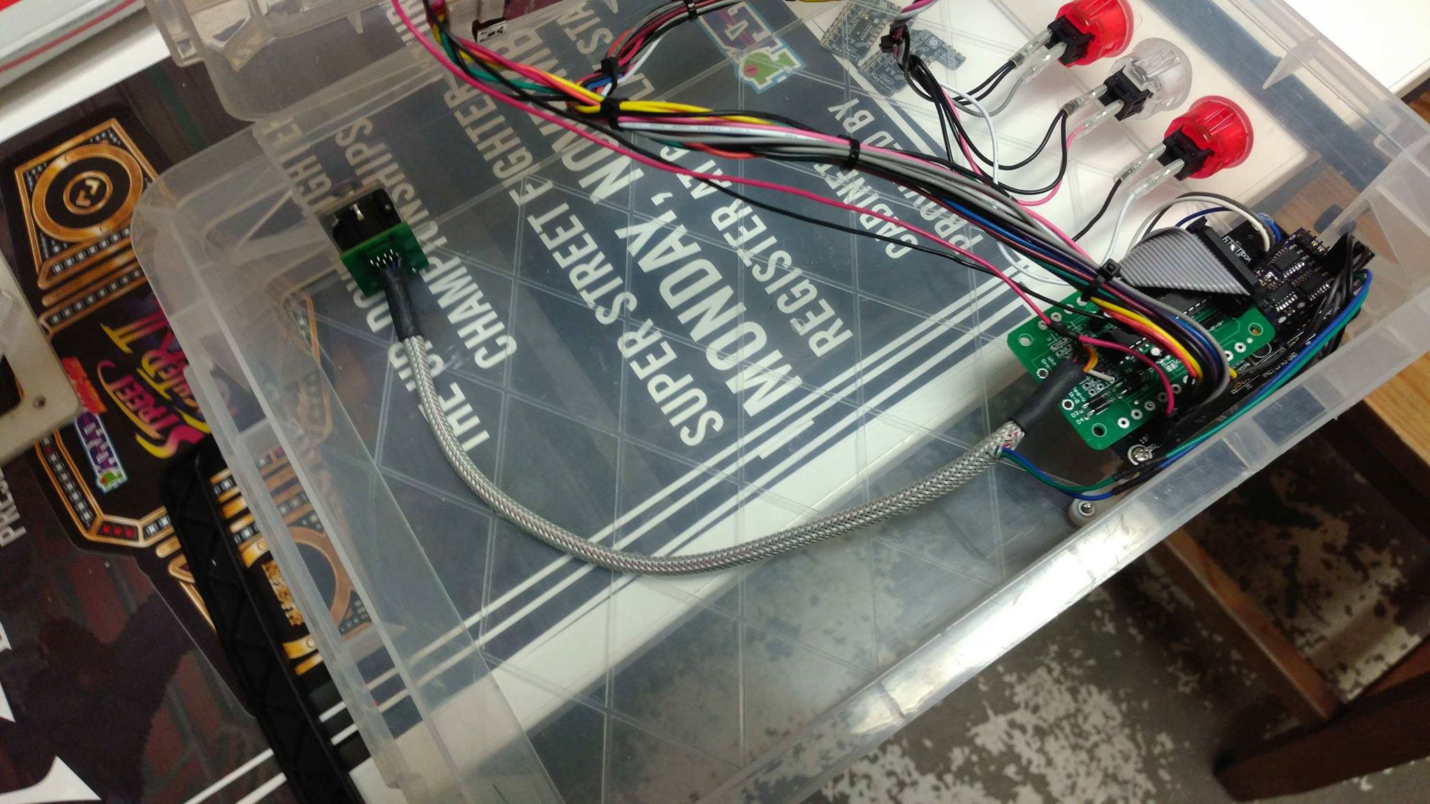
I’m currently at work but took some rough pictures last night that I’ll attach.
Right before you opened this thread up, I was thinking I’ll redo that portion since the rest seems legit.
I followed the B configuration and seems good since the PCB works as a PS3 controller. I guess a missed connection could affect the retro consoles connectivity? Either way, I’m going to redo it
Looks like you have the right idea. USB will only do PS3 and PC and if it works there the rest should work, too. Your wires look correct too based on the colors, but you should still check continuity with a meter.
@PAS.Timothy Do you know of what header I can use for the RJ45 soldering to the MC Cthulhu? I’d like to install a connection header rather than soldering wires directly to the board.
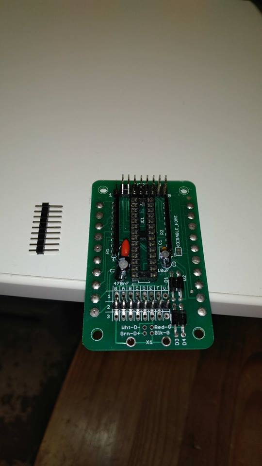
Maybe depending on the spacing of the holes you could unsolder the usb jack, solder through hole pins on the MC Cthulhu’s wire holes to the magjack breakout (like I said depending on spacing) and it may work.
The only thing I can think of that may also be an issue is possibility of the pins from the rj45 connector touching the old USB holes and shorting something out. Maybe cut the pins shorter and electrical tape or something to keep this from happening.
There isn’t one to my knowledge as all the RJ45 headers I’ve seen have a 2 row, off set 8 pin hole pattern. I don’t know why I did this, but I did. It’s a little more work than a simple RJ45 cable soldered to the Cthulhu and then plugged into a Neutrik. On the other hand, the non-passthrough version of the RJ45 jack is a little cheaper. Plus it looks kinda nice. Anyway, it seems if you want a jack on your MC Cthulhu you’ll still need to solder a wire.
I want to keep the USB intact, and I do not want to modify the MC Cthulhu at all, other than installing a connection header so that I can have a cleaner, removable install.
The idea is to have the ability to plug-in a removable cable that goes to a RJ45 port. Similar set-up to the picture you posted, Timothy, but instead of direct soldering wires to the board, it would be a connection header.
In this picture you have, you’d have to remove the RJ45 port and the MC Cthulhu at the same time, if you needed to do any servicing, or modifications, etc…
I guess I’ll just have to measure the through-hole spacing and see if there’s a header + connector that matches.
You could do something similar to what I did but instead of soldering direct to the board use .100 pin disconnects crimped to the end of an RJ45 cable and an 8 pin header soldered to the board. I actually have some at the shop that would work, I just didn’t use them because I never intended on removing the cable and to top it off, I have access to a gun for easy desoldering.
That’s what I’m looking for. So it’s a 1mm pitch spacing for those holes? I think I have a bunch of 1mm pin headers in my stash. Just gotta see about connectors.
I know how to check my version number by plugging a USB B Male to USB A Male. I unplugged my printer and plugged in my Cthulhu. Then I clicked the Apple/About this mac/System Report/USB and looked at the USB drivers, and I can’t find any information about Cthulhu or Paradise Arcade Shop or anything. So if there is firmware on this device, my Macintosh is not reading it. If My Mac isn’t reading, I have to download the firmware.
I would download the firmware, but
I have no idea how it insert it using my Macintosh.
I lost the link, (but I could find it by looking a my history) and
(UPDATE:) I tried the same thing again and noticed it’s showing up in the USB Hub as a Sega Virtua Stick version 0.06 . It’s a 12 Mb/s USB Port. Since nothing else even resembling a joystick is plugged incurrently, I assume it’s it.
When I have the most recent files available they’ll be up on the site with instructions to download. I’m not sure if there are tools available to make it work on Mac so you will probably need access to a Windows PC.
Hello @PAS.Timothy , I ordered a MC Cthulhu about a month ago, and is now in the hands of my joystick installed.
I Assume you just solder up the GABCDEFV to the 8 pins on a solderable RJ45 female.
May I know so I can tell my joystick wirer what the standard RJ45 pins correspond to on the Cthulhu?
I got the labels of the 8 holes on the Cthulhu. may I know the corresponding wires or pins or whatever you use on an installable RJ45 Female? I think my guy, Stan, will know what to do, once the corresponding pairs are given.
Hey @redijedi808 may I have the list of corresponding RJ45 wires to the GABCDEFV. It looks like orange=A, blue=C, green=e, and brown=V
The other 4 wires look white. Not White striped with something else, or something else with white. What way do you tell the 4 white wires for the G, B, D, and F?
And would any solderable female FJ45 adeapter have the proper colors for easy color coding?
I don’t know how to solder it myself, I’ll email this forum to my joystick installer.