Edit again:
I turned this into a pdf. Please download this tutorial here. Copy it, share with your friends, Host it on your website. IDGAF.
PDF version of this tutorial
Edit:
Photobucket doesn’t allow free image hosting anymore so this thread/tutorial is probably done for. I don’t have the time to move my images to another free hosting service. I feel this thread is possibly horribly outdated as it doesn’t cover this generation at all. If anybody wishes to copy my images and update this thread to a new thread, you have my blessing. Here is my photo album for this thread.
Edit:Also Dreamcast and 3DO
Intro
This post is a rewrite of Acceptable Risk?s RJ-45 Tutorial. This was posted to include new info such as recent console support added because the pinouts are spread out in the Cthulhu thread. Also I instead uses a Pass through over a keystone punch down type jack.
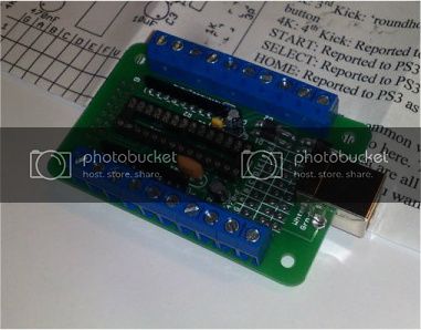
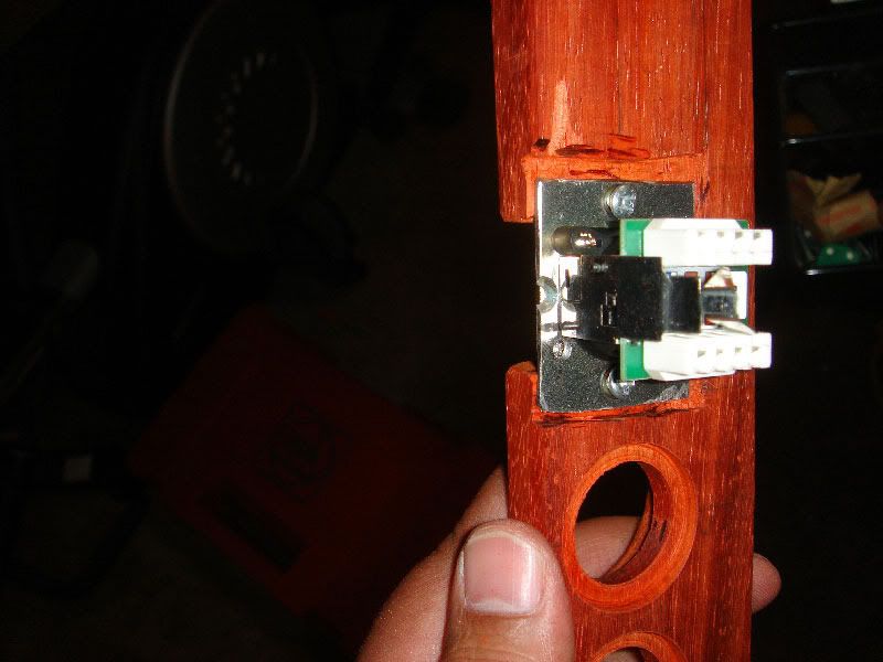
The MC Cthulhu is a purpose built PCB for hooking up with arcade joystick components. To work with different consoles, you only need to solder wires from a controller extension cable to the appropriate spots. If you look at the top op the pcb there are 3 rows of solder points with columns labled “GABCDEFV”. Each extension cable wire must be soldered on to the appropriate column. When plugged in, the MC Cthulhu PCB can autodectect what system it is plugged into and then make your joystick work for that supported system. Be sure to download the latest firmware to ensure that all of the console cables you make will be compatible.
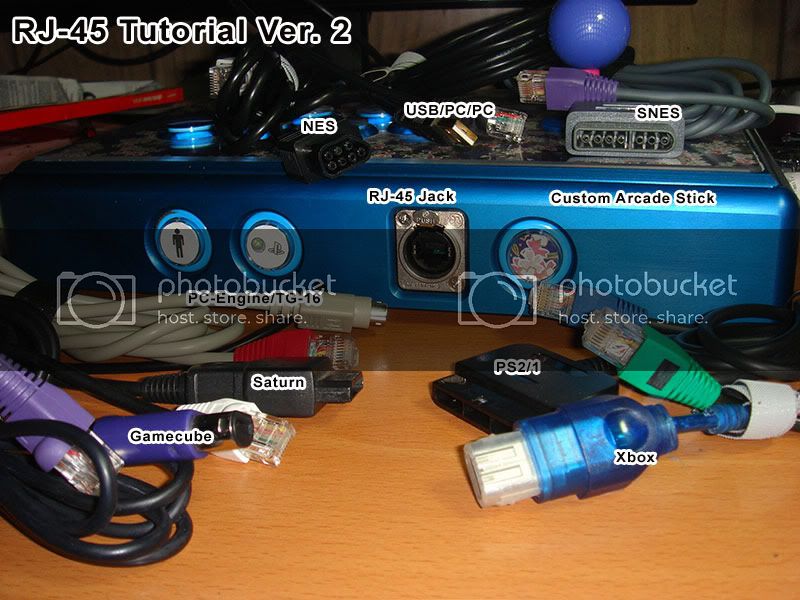
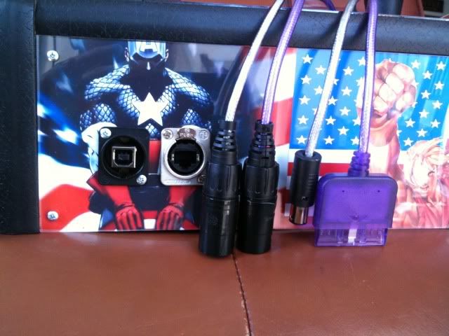
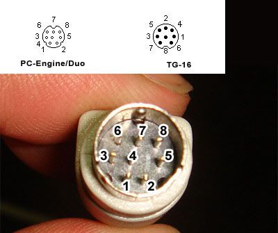
Originally the MC Cthulhu was able to support 5 consoles using 3 cables, therefore only 3 rows, but now it has grown to include many systems. Because there are 8 columns for system cables a Ethernet jack was a natural fit. The connecter used is typically an RJ-45. If you want to do a dual mod with Xbox 360 pad then you should check out this tutorial.
http://forums.shoryuken.com/t/rj-45-mc-cthulhu-imp-xbox-360-dual-mod-tutorial-diagram/92427
Kitty info Update: If you dual modded your stick with a Kitty board, they come preinstalled with a RJ-45 jack. If you connect that to a RJ-45 pass through, then you can use the same cable pinouts for making your own custom cable.
Begin Tutorial
Tutorial Parts 1 and 2
Spoiler
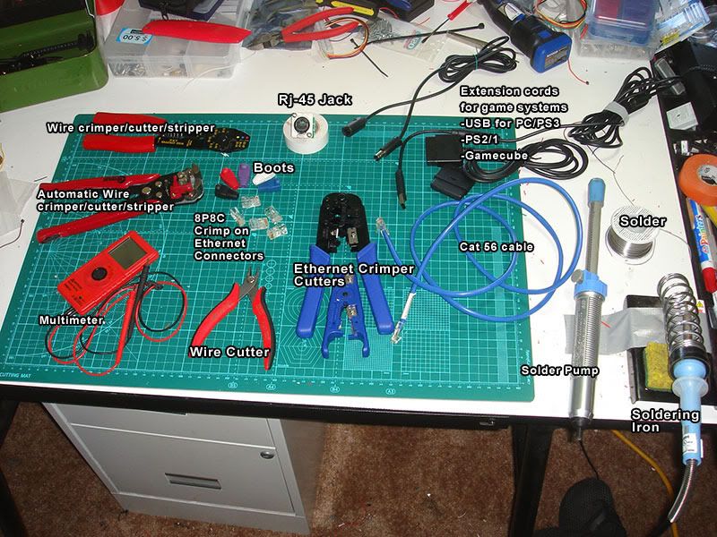
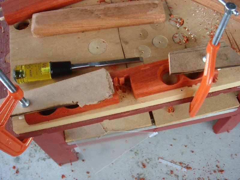
Supplies List:
MC Cthulhu
Arcade stick case and buttons.
Soldering Iron and Soldering supplies
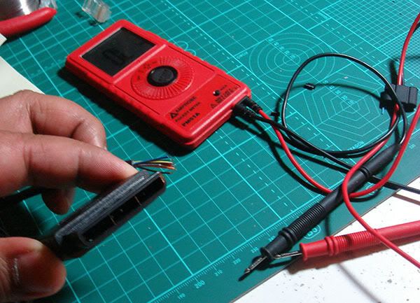
Digital Multimeter (Recommended feature: beeping continuity tester)
Wire stripper/cutter
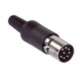
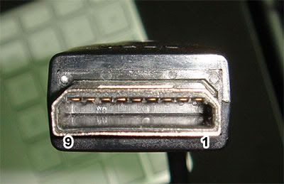
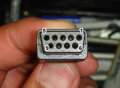
Neutrik or SwitchCraft RJ-45 Jack.
Cat 5 or Cat 6 ethernet cable. For pass through you need a cable with a connector at the end.
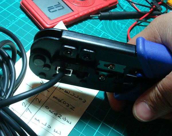
Cat 5/6 Crimper and wire cutter/stripper.
Cat 5/6 8P8C crimp on Connectors.
Extension cables for systems you want to use
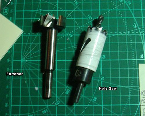
24mm drill bit (forstner or Holesaw) for mounting hole and drill.
(optional)
Ethernet boots
Neutrik ruggedized boots for use with Neutrik Jack.
Hammer
http://i730.photobucket.com/albums/ww301/rtdzign/RJ-45%20Rewrite%20ver2/RJ-45_Tools_Supplies.jpg
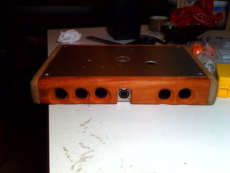
** Part 1: Mounting the RJ-45.**
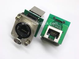
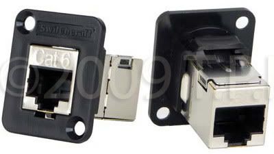
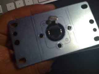
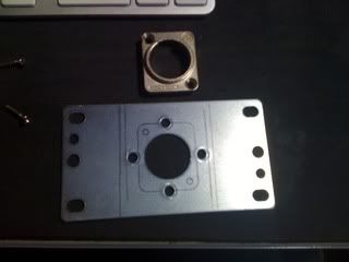
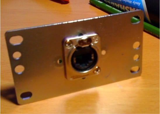
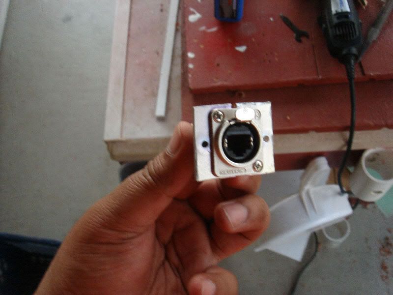
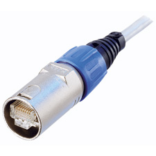
I think it was Robokrikit that first linked the community to these. These are Neutrik RJ-45 panel mount jacks, available at lizardlick.com.
http://i730.photobucket.com/albums/ww301/rtdzign/RJ-45%20Rewrite%20ver2/ne8fdp_thumb.jpg
If you have a Plastic arcade stick Like a TE or SE or Hori
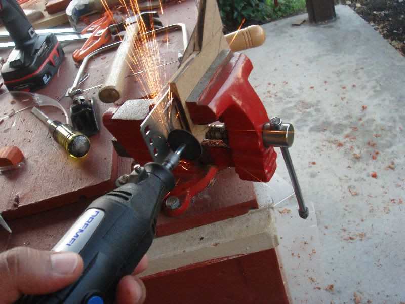
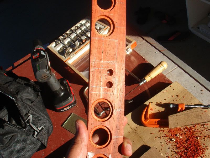
You will need to find a suitable place to drill a 24mm hole. 15/16 inches is equivalent to 24mm. Make sure before you drill a hole that you have enough space inside for the internal parts and can plug in the cable to it without obstruction.
http://i730.photobucket.com/albums/ww301/rtdzign/RJ-45%20Rewrite%20ver2/Placing-Neutrik-Hole.jpg
Pictured is a Hole Saw and a Forstner bit. A hole Saw is great for plastic and metal, and will work for wood, you will have to clear out the material out of the bit with a screwdriver. Forstners are great for wood an plastic, but do not attempt to cut metal with a forstner bit.
So if you drill a 24mm hole you can then use the mounting plate to drill the 2 mounting holes.
http://i730.photobucket.com/albums/ww301/rtdzign/RJ-45%20Rewrite%20ver2/DrillBits.jpg
For a wood case it is recommended that you use a switchcraft RJ-45. I think it was Voltech that first used these.
http://i730.photobucket.com/albums/ww301/rtdzign/RJ-45%20Rewrite%20ver2/SwitchCraftRJ-45.jpg
If you must mount the Neutrik in a wood case look to a post below.
Drill free option Update:
Recently I modded a VLX but this can also be used with a TE or any stick with a cord notch. I didn’t want to drill into my VLX case so Instead I used an Ethernet coupler and hid that away in the cord compartment. I tied a knot in my ethernet cord so that the cord would not be pulled out of the notch used for the default usb cord. For a TE, you would cut off one end of the ethernet cable and then feed it through the hole previously used by the USB cable. After it is through the hole tie a knot in it. With the cut end on the inside you can then solder to the G-V row.
http://i730.photobucket.com/albums/ww301/rtdzign/VLX%20360/th_1b827ab6.jpg http://i730.photobucket.com/albums/ww301/rtdzign/VLX%20360/th_2cf280a1.jpg
Part 2: Soldering on the ethernet cable to the MC Cthulhu
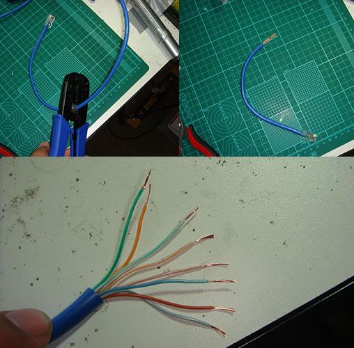
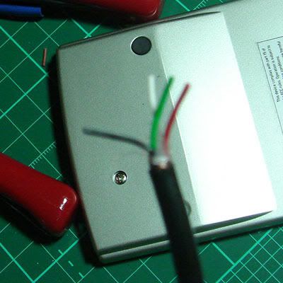
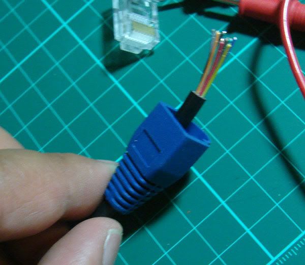
To start you would cut off maybe a foot off a cat5 or cat6 ethernet cable. The length should be long enough to reach where the RJ-45 jack is on your arcade stick. Strip off maybe a inch or two off the outer insulation and untwist the cables.
http://i730.photobucket.com/albums/ww301/rtdzign/RJ-45%20Rewrite%20ver2/CutStripCat5.jpg
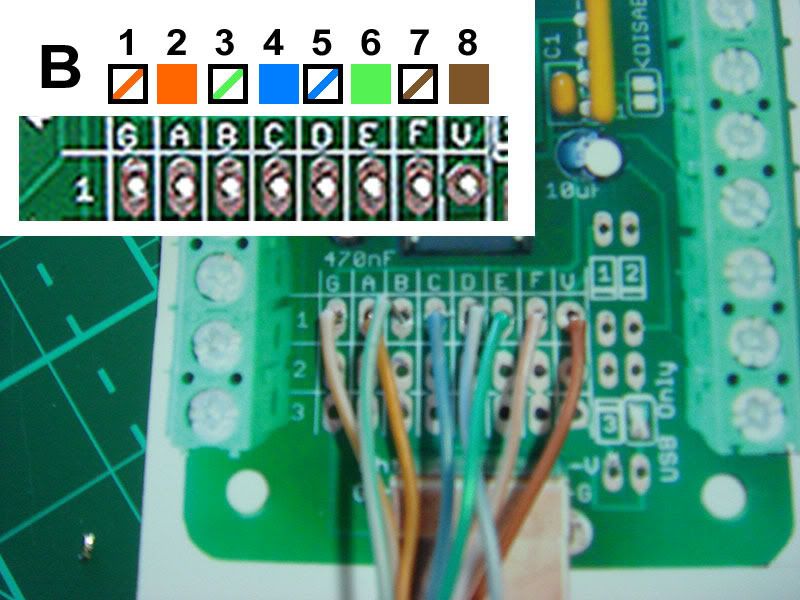
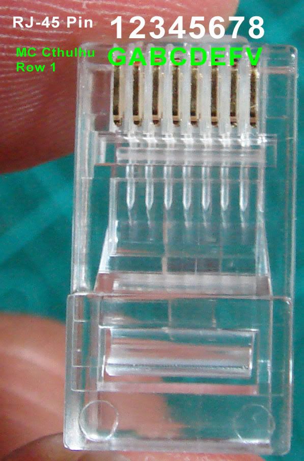
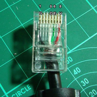
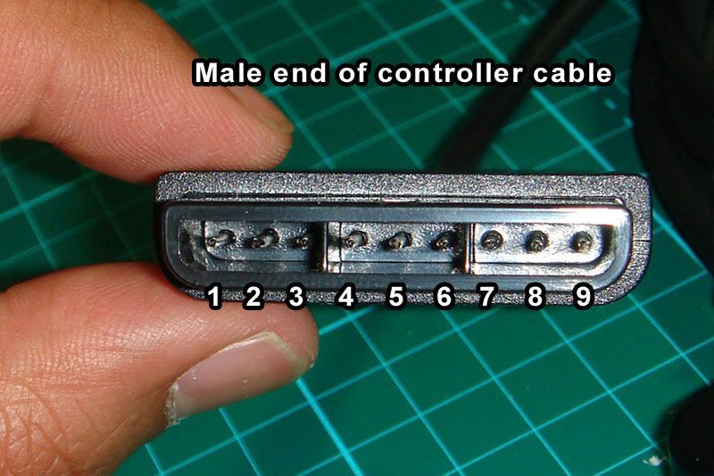
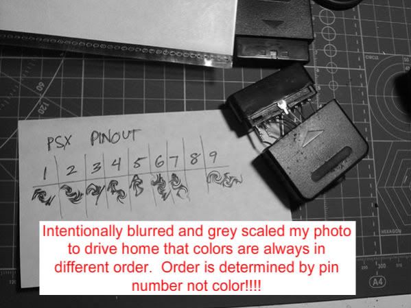
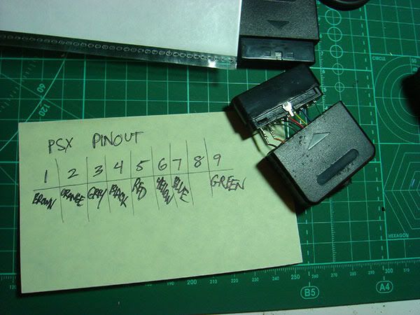
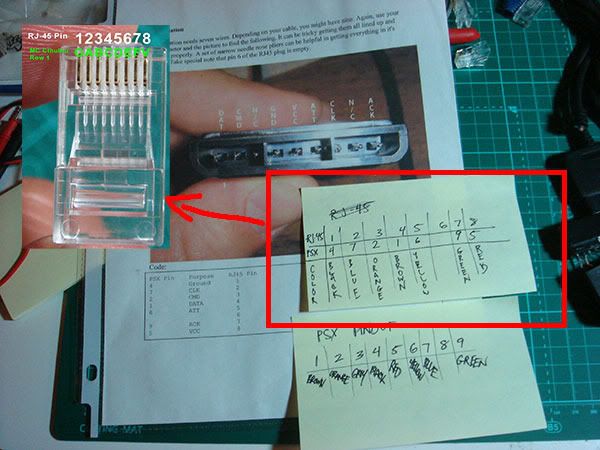
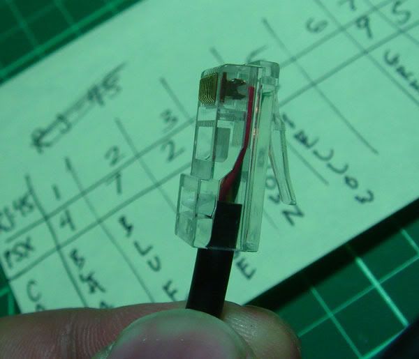
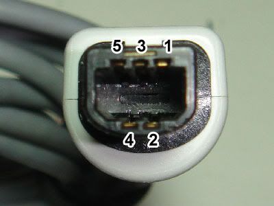
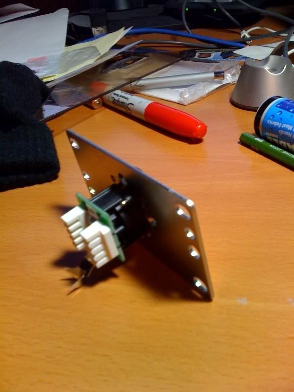
You want to use Ethernet Tybe B layout as most networking cables come in that wiring order. You need to take the 8 wires and strip off 5 mm off the ends and solder them to row 1 using the following diagram. If the are stranded like pictured above then you want to twist and tin each cable end with some solder so it goes in easier. Each of those colored wires corresponds to a letter on the GABCDEFV row.
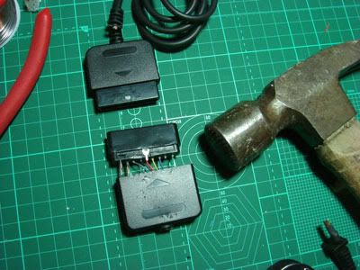
It also helps if you solder on to an actual MC board instead of a picture of the board. (note pictured on the paper is a ps3 cthulhu, which is identical in appearance except for 4 diodes to the right of the G-V rows)
http://i730.photobucket.com/albums/ww301/rtdzign/RJ-45%20Rewrite%20ver2/Cat5eSolderedonBoard.jpg
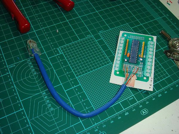
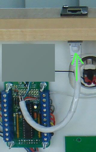
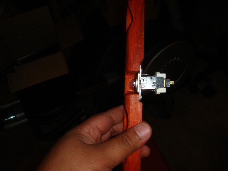
Now you just plug it into the RJ-45 pass through port.
http://i730.photobucket.com/albums/ww301/rtdzign/RJ-45%20Rewrite%20ver2/PlugIt_intoPort.jpg

 it always gets off for me
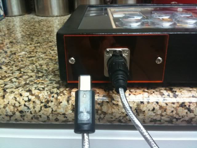