I dont know which pot values to use yet. Its just going to be the basic. If you’re worried about that though, the top board with the pots can be added afterwards once I get the values down.
just letting you know I sent the payment
I will test her out with the DC I’m still waiting on my scart for the Saturn (I’m never ordering from Electric quarter agin)
Hey toodles do you happen to have a spare generic pcb board to mount a scat port like this if so could I get one off you with this order let me know what ever it cost
Nah man I dont. If I could find a reliable place to get through hole scart connectors, id happily make a break out board and spare a few.
looks like I’ll get the proto board tomorrow I need to solder it together right? just checking I need to pick up solder
I just received it tootles it looks beautiful let me get the iron out and I’ll see if I can get some screen shots
So far the DC is working beautifully I just need to figure out whats up with the Saturn through the scaler I believe its not getting enough juice I soldered the two points on the pcb to get juice from the Vsync now I’m going to see about doing a direct 5v connection and unsolder the Vsync points
I also made a plexi and purchased some stand-offs so I will post some pic’s later tonight
I made those spots on the side for screw terminals for adding 5v from whatever. Frankly, I think the chips are pretty free as far as voltage ranges go. If you have a three AA or AAA battery holder, hell maybe even a CR2032 battery holder, you can rig up power pretty easily.
I’ve been thinking of expanding it slightly to include a way to make the lines thicker; darkenning two at a time, maybe even four at a time. Should be easy to implement.Im thinking with the higher res inputs, it’d help make the scanlines more visible.
I look forward to seeing what you post up.
cool ideas do you know why its working through the dreamcast vga box and not through the scaler+saturn do you think its a voltage issue? I haven’t tryed to directly connect it to the 5v from the scalier pcb yet
also are both those solder bridge points under the vga port there to gather voltage from Vsync its hard to read the pcb I know one is but was not sure about second one
Best guess would be no power on the VGA VCC pin. Disconnect the solder jumpers for BOTH of the power jumpers on the bottom, and run a wire from the ‘screw terminal’ +5v/VCC point to an open power spot on the scaler and I think it’ll make all of the difference. Be aware that the ‘power from VGA VCC’ jumper has a copper trace in the middle that would need to be cut with an Xacto or dremel.
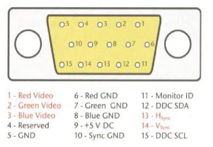
One connect the board’s power to the ‘VGA VCC’ (pin 9) and the other connects boards power to the Vsync line.
so do I need to connect them both to
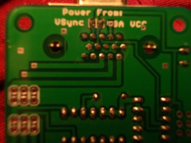
so just to be clear I should cut the trace from the right jumper shown in the pic to where is connects to pin 9 or cut the trace to the screw terminal on the far right side of the pcb
also I forgot to mention I’m going to be running a vga splitter so I can input Dreamcast VGA and the scaler imput separately to the scanline generator.the DC VGA box does not work connected through the scaler and since its not needed I’m going around it. should I power the scan generator separately with its own 5v power supply?
Do not ever connect both of those jumpers! It’ll connect pin 9 to pin 14, and mess up the vsync signal.
From what I can see on my YUV->VGA, (model VGA-1P), the VGA pin 9 is not connected to anything. If I were in your position, the easiest thing to do would be to connect the VGA pin 9 to the regulated power supply, meaning modifying your YUV->VGA. There’s a spot on the bottom that it can be tapped from. My thinking is that if you do that, then your scanliner will always be powered when the YUV->VGA is used, and of course is powered using the DC VGA box. If you’re cool with doing that, let me know and I’ll get a pic up of where to do it, and your scanner will work on both DC and YUV->VGA without modification, even through the VGA switchbox.
And remind me the family code of the chips, the letters after the 74 on the chips before the rest of the numbers.
whoops! so I only connect the left jumper right
yeah show me a pic of what to do I’m never scared to do a little finagling I only spent a $20 on it so I’m cool
Remove the solder from both solder jumpers on the scanner. As long as you didnt cut the trace, there will still be a connection between the solder jumper pads on the right, which is what you want. If you do the YUV mod I describe, then the scanner will get its power from the VGA VCC pin.
For the RGB->VGA mod, I’d recommend a thin 30 gauge wire, and DEFINITELY insulated wire. You want to connect the two points and only those, no stray coppy touching anything other than those two points.
The two spots to connect are circled in red.
http://img198.imageshack.us/img198/2747/img0775tx.th.jpg
ok so with the wire soldered like you pictured above
I tested my Saturn and it caused the screen to go darker no scan lines it just darken the whole screen in only one of the modes I forget its either with even or odd but the other does not work position registers nothing
also I went back and tested the direct connection with a dreamcast the Vsync jumper has to be soldered together or has to be powered by 5v power source but it does not work without the jumper being soldered/outside 5v power source
Damn, then Im misunderstanding something somewhere in the VGA signals. Rig it so it works for you obviously, and I’ll start checking things under an Oscope when I can.
Its all good I know what I was in for when I signed up
Do you have any ideas off the top of your head that I could try/research for the scaler input