Project Box Controllers: A Guide to Modular Controllers

Edit: Photobucket doesn’t allow hosting anymore so this thread/tutorial is probably done for. I don’t have the time to move my images to another free hosting service. If anybody wishes to copy my images and update this thread to a new thread, you have my blessing. Here is my photo album for this thread.


Post 1: Introduction

What is a project box joystick and why would I want to make one?

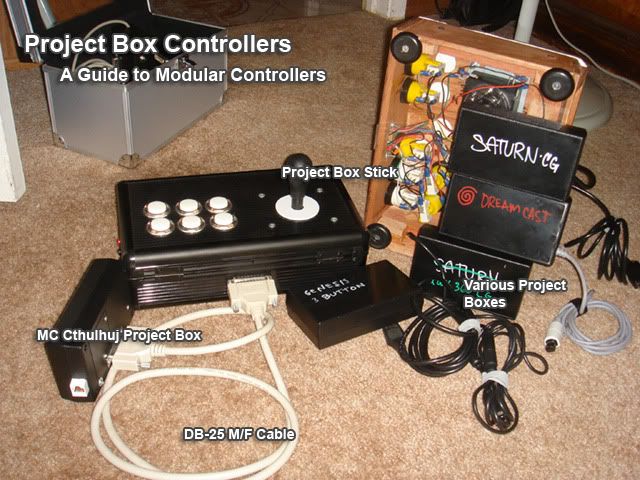
A project box joystick is an arcade stick that has a connector on the back that allows for external controller PCBs to be plugged into the joystick. On a basic project box stick, there is no controller PCB (printed Circuit board) for a game system included in the box housing the arcade parts. This is different from most sticks that have the PCB inside the box.

Instead all of the buttons signals are wired to a D-sub port mounted to the exterior of the stick. A hacked controller pcb would then be wired to a mating D-sub port and enclosed in some sort of container, usually an electronics project box.

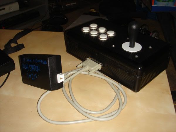
Using this method, you can have one arcade joystick, and can switch up multiple project boxes for various systems.
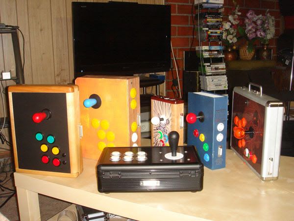
To see some examples you can visit this thread:
http://forums.shoryuken.com/t/show-us-your-project-boxes/61478To see my

There are many reasons to use project box sticks. For example If I wanted to make a Mortal Kombat stick, I would make a project box stick for that. Because I already have a couple of project boxes hacked in PCBs I could just connect the appropriate connector on the back. I also make many controllers, but don’t feel like investing in a controller PCB for every one I make, and opt to just make it a project box stick. I also have a Korean and American parts arcade sticks that are seldom used.

Introduction…

Spoiler

First before we make a project box stick, we must understand how creating a regular joystick with a single PCB works. First we must make sure that we only work with Common Ground controller PCBs to make life simple.

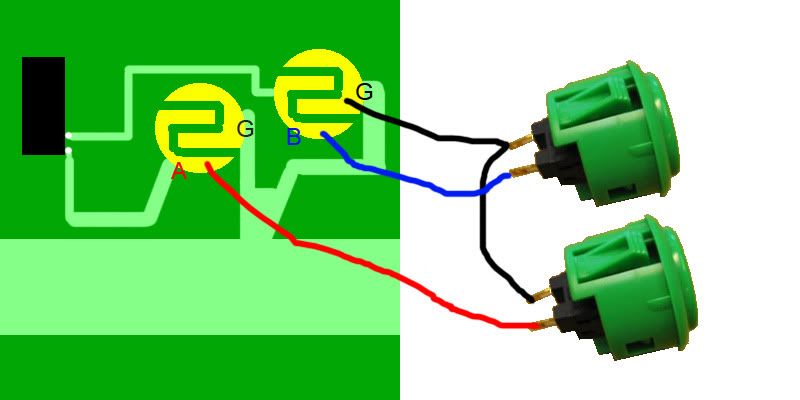
For starters we will look at how a single button is hooked up.
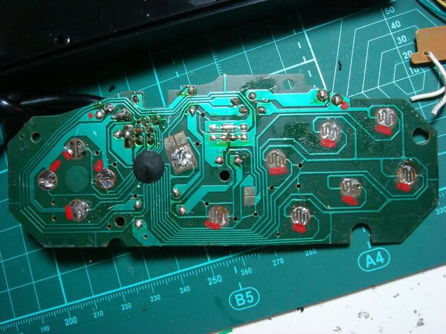
There are typically two terminals on a button. In the case of 3 terminals ignore the terminal that is labeled as ?NC?. One terminal is hooked up to a signal on a PCB via soldering or screw hole and the other is connected to a common ground. You will notice on the circuit board that the side that is common ground is linked to other buttons through the circuit paths. That is the nature of common ground, one side of every switch is connected to this “Common” Ground. The Signal will typically go directly to a pin on the IC chip. Sometimes the ICs look like black chips and other times they are oval blobs . PCBs that are not common ground that require two distinct wires per button do not jive well with a DB-25 or DB 15 port if you want all buttons to function.

http://i730.photobucket.com/albums/ww301/rtdzign/ProjectBox_Tutorial/TwoButtons.jpg

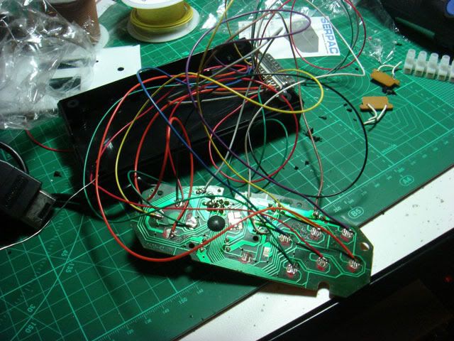
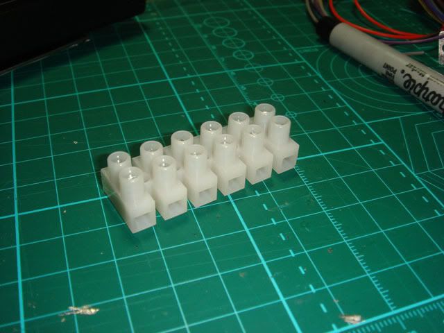
Common ground pcbs allow you to make a single wire to be connected to all points in a process called daisy chaining. This is important because it allows you to route a single ground through a pin in a DB 25 connector. Now let us look how a basic 1 pcb stick is wired up. You have a stick and it is wired to the signals and grounds on a PCB like so. In this case the PCB in enclosed inside the stick.

http://i730.photobucket.com/albums/ww301/rtdzign/ProjectBox_Tutorial/TraditionalPCBHookup.jpg

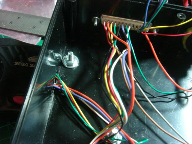
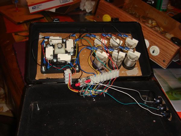
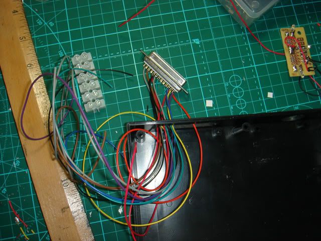
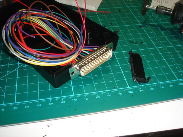
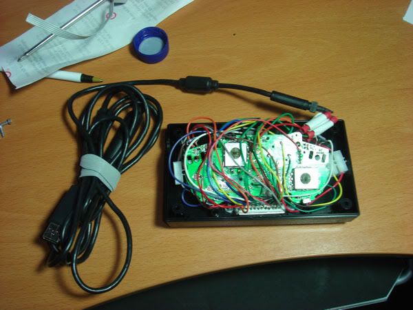
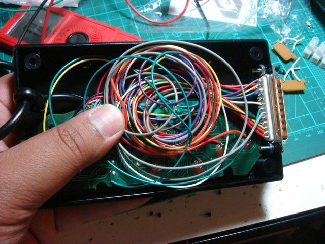
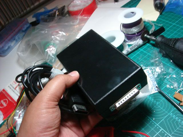
Later I will talk about how to go about putting a DB-25 port on a stick but for now here is an image of what the wiring of a project stick looks like. The PCB is encased in some sort of non conductive enclosure. Typically a project box. Mounted on the project box is a male DB-25 port that connects to the arcade stick. All of the button an joystick signals connect through the port.

http://i730.photobucket.com/albums/ww301/rtdzign/ProjectBox_Tutorial/ProjectBoxSetup.jpg

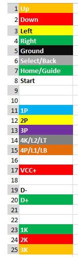
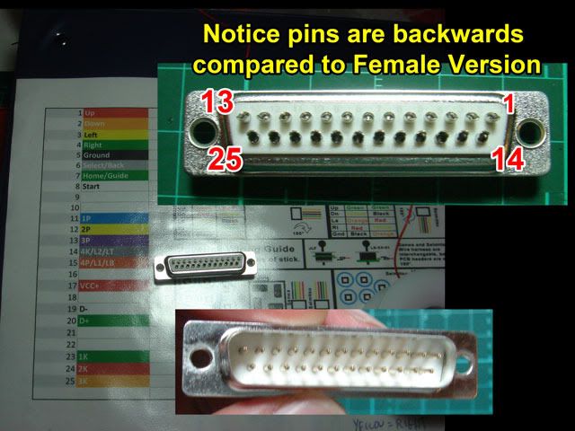
What we need to do to to make a project box stick is to wire the buttons to a DB-25 connector. It is important that you have a pinout diagram for wiring buttons and keep it for future use. While there is no rule on how to do a project box, I laid out my key to take into account the placement of buttons and joystick directions according to my female DB-25 port on my stick.

http://i730.photobucket.com/albums/ww301/rtdzign/ProjectBox_Tutorial/DB25_RJ45B_JoystickGuide-1-1.jpg

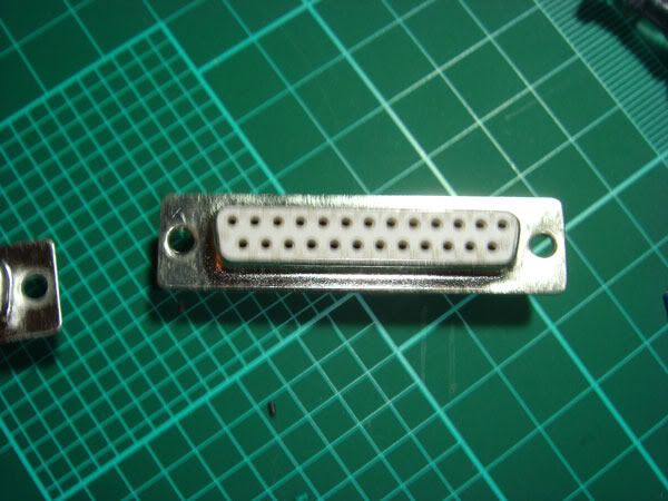
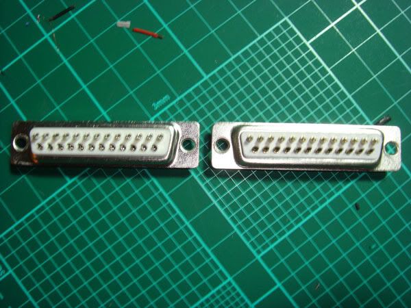
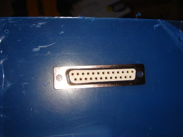
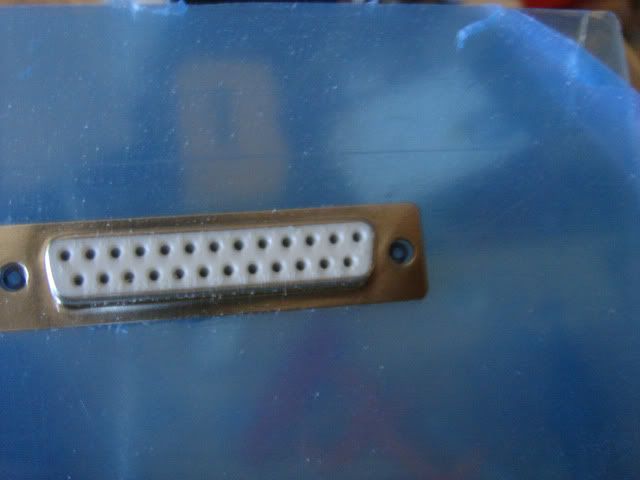
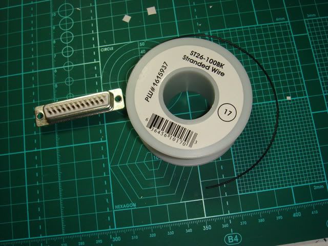
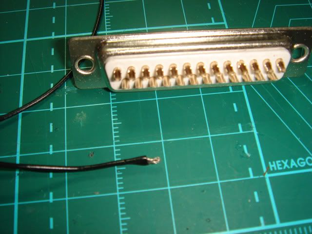
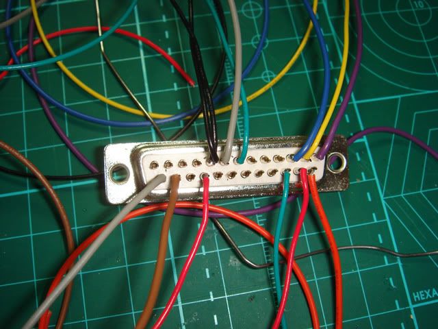
Here is a female D-Sub 25 pin connector or DB-25. It is difficult to see in this photo, each pin is numbered. A male version is also numbered and the numbers are reversed so that they match up.

http://i730.photobucket.com/albums/ww301/rtdzign/ProjectBox_Tutorial/DSC03900.jpg

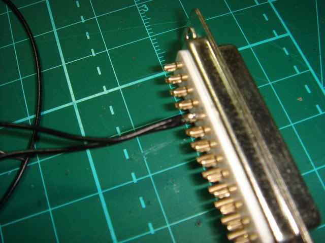
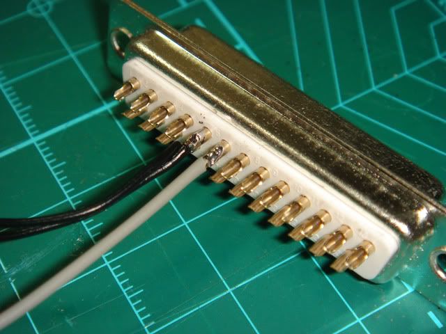
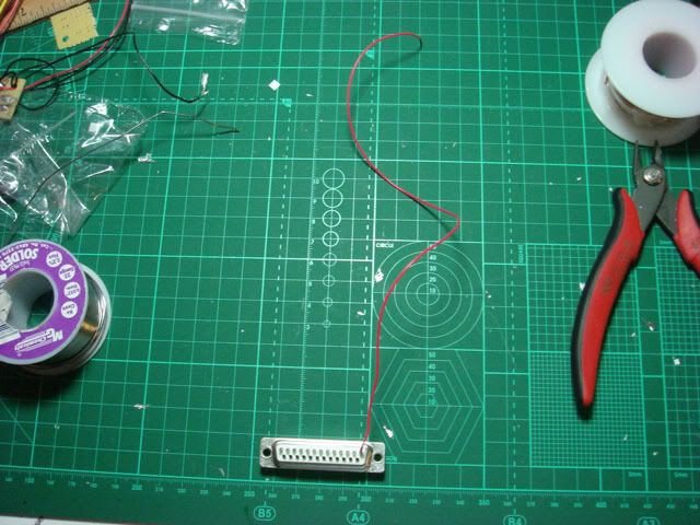
This is a picture of the back of the D-Sub connectors. These are the solder cup versions. I recommend these over the crimp style because the crimp style has flakey reliability.

http://i730.photobucket.com/albums/ww301/rtdzign/ProjectBox_Tutorial/DSC03902.jpg

You can also use a DB-15, but for a complete stick with 4 directions and 11 buttons and 1 ground for a console such as PS3 or Xbox 360, you will have to drop either triggers or a guide button and or place that on the project box. Below is a crimp on DB-15 male port. If using a DB-15 it is suggested that you make it Neo Geo Compatible in the case you have a Neo Geo, but more about that later.

http://i730.photobucket.com/albums/ww301/rtdzign/ProjectBox_Tutorial/DSC03907.jpg

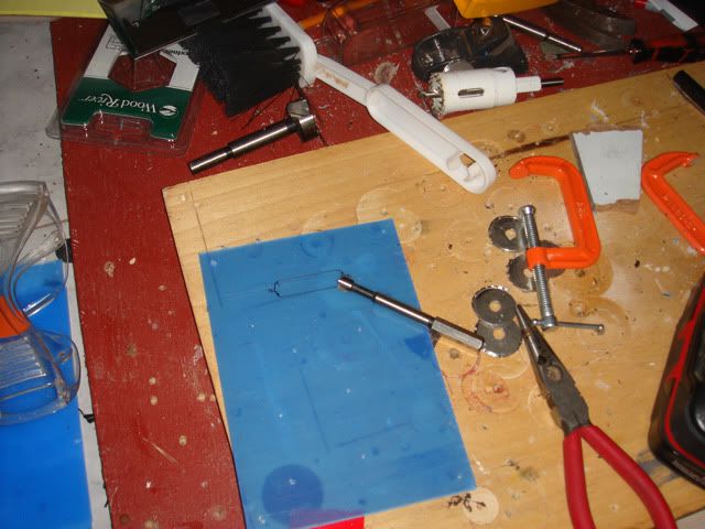
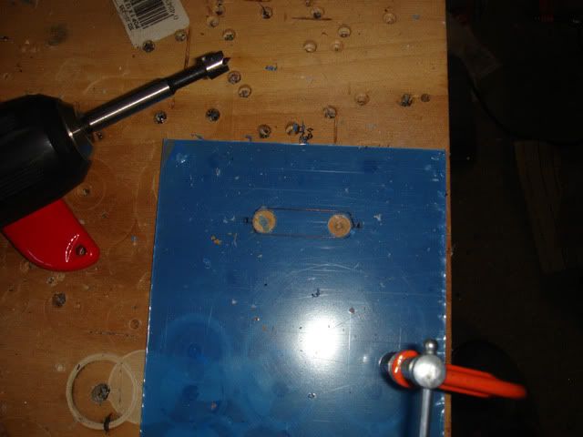
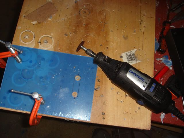
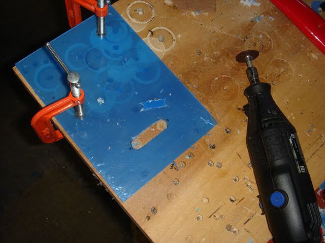
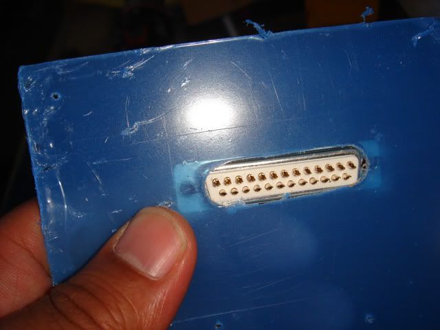
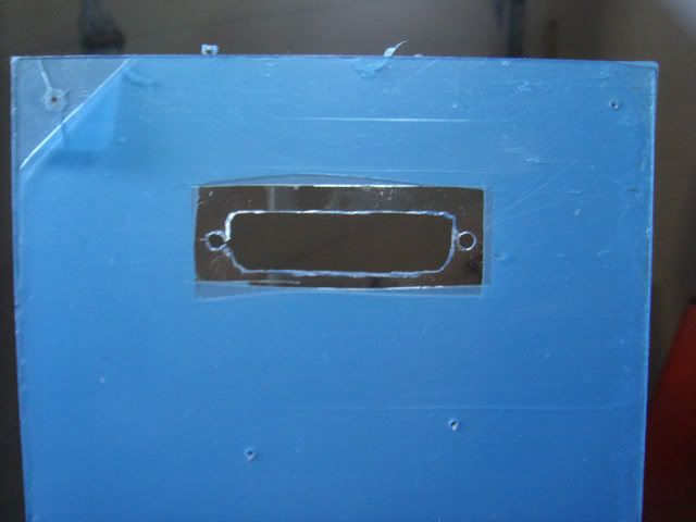
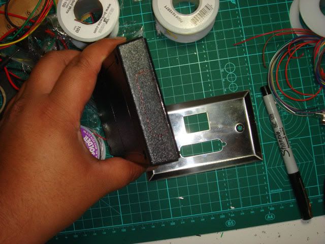
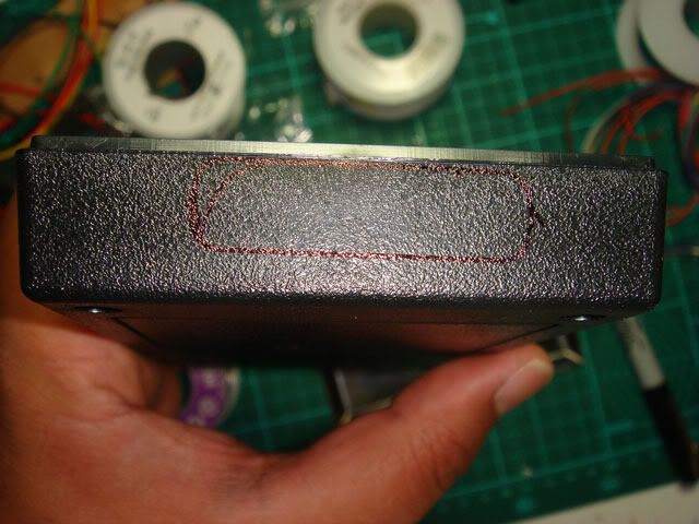
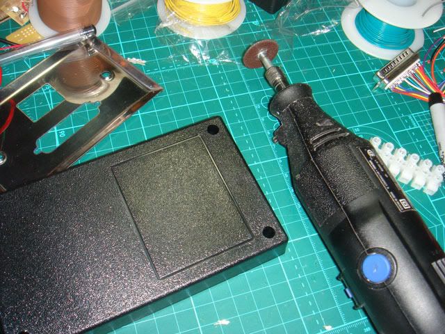
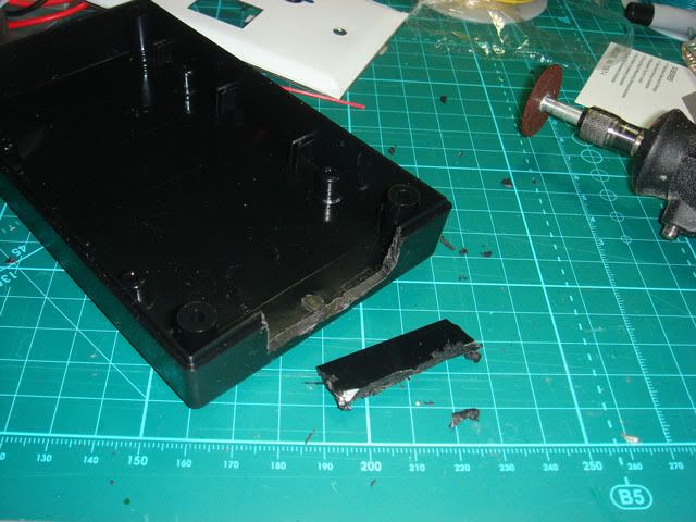
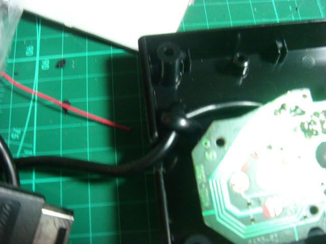
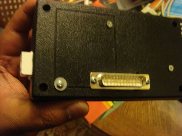
These connectors are mounted on the back or side of a stick. Wood sticks are more difficult to mount a DB connector while plastic is easier. Typically you have to drill and dremel a hole to mount it into plastic. In wood it is more difficult. Ideally the use of a router and drill is best, but it is possible to get by with a drill, chisel, and dremel. I use 4-40 machine screws to mount my D-Sub ports.

http://i730.photobucket.com/albums/ww301/rtdzign/ProjectBox_Tutorial/DSC03885.jpg

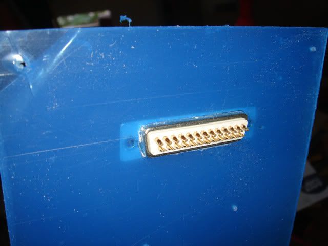
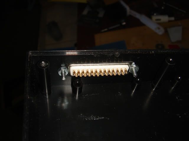
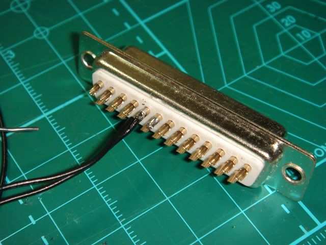
Inside close up of a DB-25 port.

http://i730.photobucket.com/albums/ww301/rtdzign/Dpad_Hybrid/DSC04007.jpg

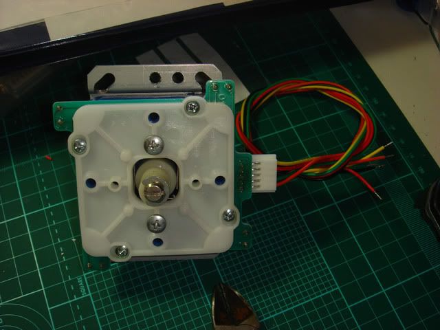
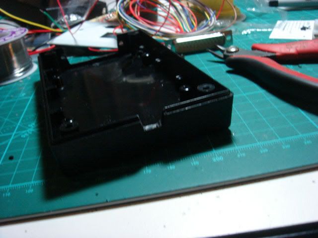
Inside a MC Cthulhu Project box with a RJ-45 port.

http://i730.photobucket.com/albums/ww301/rtdzign/ProjectBox_Tutorial/DSC03878.jpg

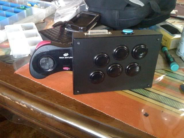
The reason why this is titled project box controller is that it doesn’t have to be a joystick. In this case I made a Franken Fightpad that uses a project box connector. So technically it is not a joystick, just a fightpad on steroids.

http://i730.photobucket.com/albums/ww301/rtdzign/Dpad_Hybrid/385bbded.jpg

(To be continued…)

Building the stick and installing a DB-25 port.

One of the first things that you should start on is creating a DB-25 or DB-15 port on the back of your stick. If you are building a wood stick from scratch, and have a plunge router, you should build a DB-25 port on the back side before you assemble and glue the stick together. If you are the type of person who owns a plunge router I’m assuming that you already know what to do.

Most likely you will have a already built stick or are modding a plastic commercial stick. Since I have none to hack I will show how to mount a DB-25 on scrap of acrylic.
Pictured below is a DB-25 wall plate that I bought at a Fry’s electronics. Not sure where you can get them but I use a sharpie to draw where I need to cut for my DB-25 port.

Installing a DB port

Spoiler

For plastic cases, I suggest that you remove everything from the inside of you stick, especially near where you will cut the port. Nothing like a drill busting through to break your components. Figure out a way to secure your stick in a vise or a table with G clamps. I like to use a 3/8 forstner bit to drill holes on the two sides. DO NOT drill for the side mounting holes yet. We save that for last. Oh and don’t forget, ALWAYS WEAR SAFETY GLASSES WHEN WORKING WITH POWER TOOLS!

http://i730.photobucket.com/albums/ww301/rtdzign/ProjectBox_Tutorial/DSC04099.jpg

http://i730.photobucket.com/albums/ww301/rtdzign/ProjectBox_Tutorial/DSC04100.jpg

I then take my dremel and cut along the inside of the line with a cutting wheel. If you are doing wood, at this step you would drill more holes and use a chisel, or router.

http://i730.photobucket.com/albums/ww301/rtdzign/ProjectBox_Tutorial/DSC04101.jpg

http://i730.photobucket.com/albums/ww301/rtdzign/ProjectBox_Tutorial/DSC04102.jpg

Hopefully you cut a slot slighter smaller than it needs to be or maybe just perfect. Now you will try to test fit to see if you can get the DB connector seated in the hole properly. Taking a look at how it fits, you will need to make small little adjustments with the dremel until it falls in very nicely and hopefully straight.

http://i730.photobucket.com/albums/ww301/rtdzign/ProjectBox_Tutorial/DSC04103.jpg

After some careful cutting with the wheel.

http://i730.photobucket.com/albums/ww301/rtdzign/ProjectBox_Tutorial/DSC04104.jpg

http://i730.photobucket.com/albums/ww301/rtdzign/ProjectBox_Tutorial/DSC04105.jpg

At this point you want to take a sharpie and re draw in the side mounting holes using the fid DB connector. Because the hole was hand made the placement of the holes might have shifted. saving this for last works best to make sure that the holes are aligned when seated. I drill these with a 1/8 inch bit.

http://i730.photobucket.com/albums/ww301/rtdzign/ProjectBox_Tutorial/DSC04107.jpg

http://i730.photobucket.com/albums/ww301/rtdzign/ProjectBox_Tutorial/DSC04108.jpg

If you have a thin enough case you should try to get some D-Sub Hex screws. You can screw the DB-25 connector into it.

http://i730.photobucket.com/albums/ww301/rtdzign/ProjectBox_Tutorial/yhst-90432262887525_2121_202492852.gif

Since I don’t feel like ordering them I take some 4-40 machine screws to bolt it down.

http://i730.photobucket.com/albums/ww301/rtdzign/ProjectBox_Tutorial/DSC04111.jpg

Soldering to the DB port.

Now that we have a proper mount for the port, take it off and now we need to solder our wires to it.
I makes sure that I have my wiring pinout handy. If you look at the way I laid out the pins You will find that the positions of signal pins helps with how a common joystick is laid out.
The left picture is the pinout the upper right is how those pins correspond. The lower left picture shows an almost finished port.

http://i730.photobucket.com/albums/ww301/rtdzign/ProjectBox_Tutorial/PinoutPlusPictures.jpg

So now we need to solder to the port. It is not practical to try to solder to this port when it is mounted in your joystick so remove it. I happen to have wires in 10 colors and use it to help me quickly figure out the wiring. If you want you can use just one color of wire, so it is up to you. My preference is to use 26 gauge stranded wire because the smaller wire is easier to hook up to the DB port. 24 and maybe 22 might be okay.

http://i730.photobucket.com/albums/ww301/rtdzign/ProjectBox_Tutorial/DSC04120.jpg

The first wire that I am going to solder is the ground wire. That is located at pin 5. For the ground I usually take a piece of black wire maybe about a foot and strip it maybe 4 inches from one end the middle and fold it. I twist and fold the wire and then tin it and solder it to pin 5 on the port. This way I have 2 wires coming out of pin 5, one for the joystick and one for the buttons.

http://i730.photobucket.com/albums/ww301/rtdzign/ProjectBox_Tutorial/DSC04121.jpg

http://i730.photobucket.com/albums/ww301/rtdzign/ProjectBox_Tutorial/DSC04122.jpg

For now I will skip the directional pins, because that depends on if you have a harness joystick or have a direct to switches joystick. So now for the “select button” wire. I strip off maybe 3 mm of wire. I twist the strands so that the wire isn’t frayed and then apply some solder to it. This is called tinning. Doing this will make it easier to insert into the Pins. After you have tinned your tips, clip off any exposed wire in excess of 2mm. You want to only have a very small amount of wire exposed as you solder it to the pins.

http://i730.photobucket.com/albums/ww301/rtdzign/ProjectBox_Tutorial/DSC04125.jpg

So Select is pin 6 right next to ground. I then melt some solder to the pin, then I take the wire I tinned and insert it while the iron has it hot and melty. Make sure that the insulation goes right up to the pin and the wire is not free to bump into other pins.

http://i730.photobucket.com/albums/ww301/rtdzign/ProjectBox_Tutorial/DSC04127.jpg

http://i730.photobucket.com/albums/ww301/rtdzign/ProjectBox_Tutorial/DSC04128.jpg

I then repeat this for the rest of the buttons wires.

http://i730.photobucket.com/albums/ww301/rtdzign/ProjectBox_Tutorial/DSC04129.jpg

For the Directions it really depends on what type of joystick you have. You have a few options. For a harness joystick, you can solder the harness directly to the DB-25 port. Pictured is a harness joystick.

http://i730.photobucket.com/albums/ww301/rtdzign/ProjectBox_Tutorial/DSC04131.jpg

If you have a direct to switch joystick like an iL/Happ, JLW, or Seimitsu that does NOT END IN -01,
then you would just treat each directional switch, no different than a button.

You will also noticed that on my guide I have VCC listed on pin #17. If you have a joystick that requires voltage such as a Toodle’s JLF Spark Kit, Happ p360, Sanwa Flash, Ascii Optical, or Suzo Inductive. You will need to probe the for the voltage pin and a place to solder on the pcb when we get to the project box. Also if you are modding a stick like a madcatz se or TE with a DB-25 port and opt to keep the PCB in the stick, you will need to wire the VCC the pcb to this pin. For USB PCBs Vcc can be tapped from where the red wire solders on to the PCB.

Pictured is a iL Competition joystick. In the stick below I made use of a Eurostyle terminal block.

http://i730.photobucket.com/albums/ww301/rtdzign/ProjectBox_Tutorial/DSC03867.jpg

From here you can can bolt the DB-25 port to the hole you mounted and proceed to wire up the joystick with quick disconnects soldering or what ever your preference.

http://i730.photobucket.com/albums/ww301/rtdzign/ProjectBox_Tutorial/DSC04133.jpg

http://i730.photobucket.com/albums/ww301/rtdzign/ProjectBox_Tutorial/ProjectBoxSetup.jpg

Next up is the PCB in the Project Box
(To be continued…)

The Project box.

Here is a picture of a bunch of things needed for the project box.
The Red thing on the Left is a Multimeter.
The Black box on the middle that says, “SERPAC” is the project box. Also called project enclosure. This particular size project box seems to be the perfect size for the majority of PCBs I commonly work with. A 3rd party Sega Saturn PCB I dug up for this tutorial. A soldering iron. I also have a red paint pen to mark off what side of the switch is common ground.

Creating a Project Box

Spoiler

Closeup on this project box. While you can use what ever container, if you want to use this one, here is the info on the retail sticker. I’ve seen some people use VHS plastic cases which are very economical, and old electronics boxes. It can be anything that is non conductive. Don’t use a copper box.

http://i730.photobucket.com/albums/ww301/rtdzign/ProjectBox_Tutorial/DSC04155.jpg

So now I take my male DB-25 Connector and my pinout chart to begin soldering. If you look at the numbers molded on the connector you will see that a Male DB-25 has the pins set backwards from the what is on the female connector.

http://i730.photobucket.com/albums/ww301/rtdzign/ProjectBox_Tutorial/PinsDB25male.jpg

So now referring to my guide, I start soldering to my connector. Same as before in the previous post.

http://i730.photobucket.com/albums/ww301/rtdzign/ProjectBox_Tutorial/DSC04159.jpg

I now continue untill I’m done. I realized that I soldered for Select and Guide, I didn’t need to for a saturn PCB.

http://i730.photobucket.com/albums/ww301/rtdzign/ProjectBox_Tutorial/DSC04160.jpg

You will also noticed that on my guide I have VCC listed. You need VCC if you plan to have either or a controller pcb inside your stick, or if you have a joystick that requires voltage such as a Happ p360, Sanwa Flash, Ascii Optical, or Suzo Inductive. You will need to continuity probe the voltage pin on the end of the controller and to where the cord attaches to the PCB and find a solder for the Vcc or Voltage. The controller pinouts herewill help you find the VCC point for some systems. Google “controller pinouts” for the pcb in question. But now I’m getting off track.

Now it is time to cut up a project box. Just like the stick it is pretty much the same. I am cutting a notch in the project box. With a dremel

http://i730.photobucket.com/albums/ww301/rtdzign/ProjectBox_Tutorial/DSC04161.jpg

http://i730.photobucket.com/albums/ww301/rtdzign/ProjectBox_Tutorial/DSC04162.jpg

http://i730.photobucket.com/albums/ww301/rtdzign/ProjectBox_Tutorial/DSC04164.jpg

http://i730.photobucket.com/albums/ww301/rtdzign/ProjectBox_Tutorial/DSC04165.jpg

http://i730.photobucket.com/albums/ww301/rtdzign/ProjectBox_Tutorial/DSC04166.jpg

Then mark the drill mounting holes.

http://i730.photobucket.com/albums/ww301/rtdzign/ProjectBox_Tutorial/DSC04169.jpg

Then the notch for the controller cord.

http://i730.photobucket.com/albums/ww301/rtdzign/ProjectBox_Tutorial/DSC04170.jpg

I tie the cord in a knot where it exits the project box so it doesn’t pull the pcb.

http://i730.photobucket.com/albums/ww301/rtdzign/ProjectBox_Tutorial/DSC04172.jpg

In red I marked off where the grounds are so the other side is signals. You don’t have to do this but I wanted to save myself some photoshop time.

http://i730.photobucket.com/albums/ww301/rtdzign/ProjectBox_Tutorial/DSC04173.jpg

I proceed to padhack the wires to the pad.

http://i730.photobucket.com/albums/ww301/rtdzign/ProjectBox_Tutorial/DSC04175.jpg

Noticed that I installed the DB-25 connector first to the project box then I hacked the connector to the PCB. If I cut a hole for the DB-25 connector instead of a notch, the attached wires would have to be cut to mount the DB-25 connector. If you do this you can cut and use a few eurostyle terminals to reconnect the cuts. On one Xbox 360 PCB I hacked I soldered directly to the DB-25 and as I was cutting a hole in the project box realized that I could not mount the connector because it was a hole. The Eurostyle strip is bridging the cut cables.

http://i730.photobucket.com/albums/ww301/rtdzign/ProjectBox_Tutorial/DSC04163.jpg

http://i730.photobucket.com/albums/ww301/rtdzign/ProjectBox_Tutorial/DSC03883.jpg

Okay back to the saturn pad I just hacked. Stuff all the wires into the box and screw it together.

http://i730.photobucket.com/albums/ww301/rtdzign/ProjectBox_Tutorial/DSC04176.jpg

http://i730.photobucket.com/albums/ww301/rtdzign/ProjectBox_Tutorial/DSC04177.jpg

Now we take a DB-25 cable to link the project box to the stick. I used to attach the project boxes directly to the stick, but found an extension cable to allow me to put buttons on the back of the stick and not limit the design of my sticks.

http://i730.photobucket.com/albums/ww301/rtdzign/ProjectBox_Tutorial/DSC03895.jpg

Test and if broken find out what is wrong and fix it. If it works, have fun. Make more project boxes. I highly suggest making a project box housing an MC Cthulhu and RJ-45 port.
RJ-45 Multi Console Cthulhu Arcade Stick Tutorial Ver.2

http://i730.photobucket.com/albums/ww301/rtdzign/ProjectBox_Tutorial/DSC03878.jpg

http://i730.photobucket.com/albums/ww301/rtdzign/ProjectBox_Tutorial/DSC03876.jpg

Reserved 3: Dual Modding internal PCB to D-Sub

So in the below example I put in a dual strike PCB inside the controller and routed the cord pins through the DB-25 port. If you have a PS3 or Xbox TE/SE or common ground USB stick it is possible to reroute the cord through unused pins on the db-25 connector. How you pin that out will be up to you. Below is an example for a USB controller. Because the DB-25 connector has so many left over pins, it is even possible to do this with a Playstation joystick, provided it is common ground.

Hints for including a PCB in a project stick

Spoiler

So in a Nutshell,

-All signals and ground go to both buttons and DB-25 port.

-Voltage must be going to DB-25 and anything in stick that requires voltage. (Optical Joystick and/or LEDs)

-for the system cord, you must cut the cord and reroute wires through unused pins on D-Sub

-make a custom D-sub connector to match the wires on the PCB. Know that Ground and Voltage are two of those wires.
In the example my custom USB cable has ground at pin 5, voltage on 17 and D- and D+ on 19 and 20.

Reserved 4: making a Neo Geo compatible D-sub 15 pinout.

NeoGeo Pinout.

Suggested NeoGeo/Street Fighter Pinout for a DB-15 stick. 4P and 4K have been dropped on this Layout as every pin is used. Remember that the 5v is needed to power an optical stick or to tie the voltage if you have an internal pcb.

Suggested Layout for a DB-15. Up to you where you want Start, Select/Back, Home/Guide.

An example of a Neo Geo Compliant Stick.

Reserved 5: Quotes from other people.

Breakout boards pictures

Spoiler

FGWidget Convertor- Summary: FGWidget board is a board that lets you take a Playstation, Snes, or Saturn controller, and plug it into a box to output to a DB-25 or DB-15 port. No hacking the original pad.

How to Assemble a FGWidget Convertor

Spoiler
1 Like

Just letting folks know I got the first 3 parts done on this tutorial. The other two parts will be short additional info or optional stuff, but the main part is complete. I’ve got enough reserved spots so feel free to post after this post if you are having trouble or questions.

Nice work, man! :bgrin:
-ud

Nice writeup.
I don’t agree with crimped connections being flakey, but it’s probably not worth buying a crimper unless you’re going to be making a whole lot of connectors.

It could have to do with the brand of crimp pins or the D-sub I was using. I have a DB-15 project box with a genesis pad and it works, but the diagnosis with a multimeter is that the thinner crimp pins did not mate well to the other connector.

That’s a bit wanky. Though I did once crimp up a whole connector’s worth of pins to then discover that I had used pins for a high-density connector (which are a little smaller). IIRC those pins don’t seat right in a normal D-Sub connector though.
(I wondered why the pins didn’t seem to fit into the crimper quite right the whole time I was working on it.)
Nothing wrong with soldering though, and a soldering iron is a lot more general purpose (and less expensive) than a D-Sub crimper.

More on-topic, for mounting the D-Sub connector you used machine screws, but threaded standoffs will allow you to screw the cable into the connector (in case you really thrash around while you play, or kick the project box). Be very careful about the length though; if they’re too long the cable will not fully seat in the connector. And if you rear-mount the connector (so the metal flange is inside the box) you need to take the thickness of the panel into account.
And a small correction, the thread size should be 4-40, not 8-40.

Finally, a minor point, but I would make the connector on the project-box female. That way if you happen to accidentally drop something conductive on the connector just wrong you can’t short the power to ground (or zap yourself if you put your finger across it). Not a huge deal with 5 volts and low current though, and once you’ve started you have to keep everything the same.

Stand off screws are actually an excellent Idea. Nobody sells ones long enough for wood cases, but for a plastic case there isn’t any reason not to.
http://ep.yimg.com/ca/I/yhst-90432262887525_2121_202501728

This is an EXCELLENT guide! :tup:
I have just one question… How much “response time lag” gets added by doing it this way? Does it vary from system to system?

it’s a cool idea because you’re using a universal plug and then you make your own adaptor for each platform… i however have one plug and a bunch of adaptors instead.

Basically, there’s no extra lag for a set-up like that. Technically, there’s the extra time that the electricity takes to go down the wire which is roughly .00000003 seconds.

Well, in that case, I’m in!

If I were to hook up a 360 fightpad this way, what would the max cord length be? I have a Datel Arcade Pro (same as Paewong Revolution) with it’s original 10’ USB cable sitting inside of my project box. I then have my DB25 female coming off of that (about 3") and then a DB25 male connected to a Xbox360 dongle. I have already done a Saturn Pad DB25 to the box successfully, but have found that I prefer the oversized Dpad of the madcatz fightpad. Seeing as how I do not want to do anything to the fightpad, I thought I might be able to do it that way (described above). All continuity chcks out, but when I plug in I get the “unrecognized usb device error” on my PC. If I unplug the DB25 and replug the USB into the PC, it works fine again. The most perplexing thing is that I connected an original model 360 wired microsoft pad to the dongle and it worked fine.

Am I correct in assuming that my fightpad is probably not receiving enough voltage because of it’s energy needs and the overall length of cord?
If that were the problem, how could I fix it?

The way that it is worded, it is difficult for me to construct a mental picture of what you have setup. Lots of photos of what you have would help.

Here are the pics.
Now, as stated above, it works with the first model of 360 wired controller but not the fightpad. The original microsoft wired pad had no shield ground in it, and I think it used less energy. My DB25 is wired up for full inputs from a Paewang, as well as the 360 usb protocol. I used 4 open pins for the 360 usb protocol.
So I have D-, D+, VCC+, Shield Ground, and Ground (the same ground as was used for the other input setups)

PINOUT

  1. Start
  2. Back
  3. Turbo
  4. Home
    5
  5. Left
    7
  6. A
  7. LT
    10
  8. LB
    12
  9. Right
    14
  10. RT
  11. Y
  12. Up
  13. VCC+ (360 USB Red)
  14. D- (360 USB White)
  15. D+ (360 USB Green)
  16. Ground (360 USB Black)
  17. RB
  18. B
  19. Down
  20. X
    The shield ground is not on a pin but a separate wire run through the DB25. (360 USB Black)

I also noticed that I forgot to mention that the circle of light on the fightpad lights up in all 4 spots and then goes off. The old school xbox wired pad works normal, all lights light up, then it selects the first slot (1st player light) stays lit.

Pics here

For a first time builder: are project boxes a worthwhile learning experience?