After having done it, I would say that for a first time builder, you couldn’t find a better learning tool than building a project box. I have already built 4 sticks for my 360, but needed them “dual-modded” for PS3 console tourneys. Now as far as difficulty goes, making an old saturn pad work with a project box, was not all that easy. But for fightsticks it is cake.
http://www.blueiggy.com/main/images/stories/p1070720.jpg
Oh now I see. You only have the USB out from the fightpad. No that wont work. You cannot just take the Wires in the usb (Votage, Ground, D+ and D-) and bridge that to the Datel.
For this to work you are going to somehow need to hack each individual button and direction off the madcatz PCB and either somehow put the db-25 port on the back of the fightpad, or use some alternative to that. A smaller port might be more feasable like a HDMI port out.
Not sure what system the PCB the Datel is for, I’m assuming that it is PS3. For this to work you have to hack your pad like the stick in the pic below. Trying to do a project box mod on a fight pad is 9/10 difficulty. You have to do it like this tutorial.
http://shoryuken.com/f177/modding-saturn-pad-360-ps2-174805/

As for why your works on a default 360 pad. I would have not expected that to work at all.
Great tutorial. I put a DB-15 connector on one of my sticks a while back and made a few boxes from old VHS cases. Works great, I have the port on the stick wired for Neo Geo + a couple extra buttons for the other boxes.
The Datel Arcade Pro is exactly the same thing as the Paewang Revolution. It is for Xbox360/PS3/PC and you switch the modes by holding down turbo when plugging it in to your system of choice.
As long as I have it selected as a 360 when I plug it in to my 360 or my computer it registers the old Xbox pad. Heck it even starts to register the fightpad, it just stops really quickly! LOL
Well if that is what I have to do, then so be it. I already did the hardcore drill through the PCB and secure the solder points stuff with the Saturn pad. The fightpad looks like it would actually be easier to hack to a DB25, I just didn’t want to go to all that work if I didn’t have to.
Just wanted to confirm, Neo Geo has a female DB-15 on it? So, build project box stick with male end, and DB-15 M/F cable to connect? Also, do you know of any cables on monoprice (Or anywhere else, for that matter, monoprice is just preferred for bundled shipping) for DB-15? I looked at For only $2.17 each when QTY 50+ purchased - DB15, M/F, 1:1, Mo - 10ft | Apple Cables, but it appears that it doesn’t Neo Geo fit in the reviews.
One thing to add is that there are breakout boards that you can use inside a project box if you would prefer not to have to solder to a D-sub. I bought some from a company called Winford Engineering.
Breakout Boards (Terminal Boards) - Winford Engineering
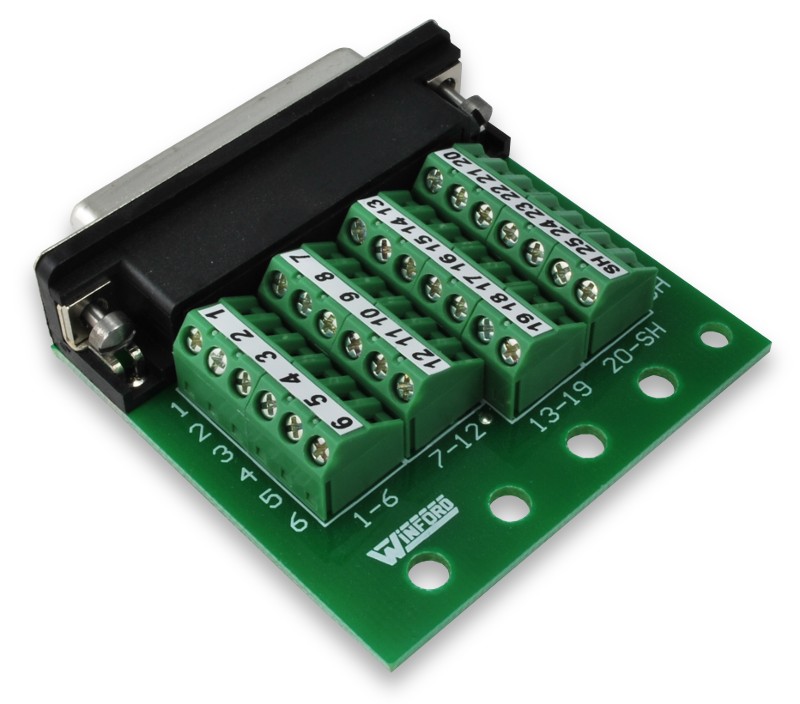
They are kind of expensive though at around $23!
However, you can find them on ebay sometimes for much cheaper prices.
http://mdfly.com/newmdfly/products/CNC/MDCDB2504/MDCDB2504_MDFLY.jpg
These are only $6 plus shipping
I’m not sure about the AES, but controller ports on an MVS (for those that have them) are male, but but the pins are so deep in the hood (yo) that a regular dsub just wont fit. The only solution I’ve found is to either wire up a standard DB15, or use a Neo Geo AES extension cord from Jamma Nation X.
Thanks for doing this by the way. I truly enjoy using the project box method and have been using it for years.
and hey, those breakout boards look sweet! I’ll totally use those for my next stick build. Soldering is best, but when I make a mistake its such a headache sometimes.
For Neo Geo extension cables if found this:
FC / NeoGeo Joypad Extension Cable - $4.50
Don’t know how reliable the website is, but if they are legit, the price looks better than what people are over charging on ebay.
Cool breakout boards suggestion Megaultrasuper. I hope you don’t mind but I quoted you and put it in the 5th post
You can also do what I did if you have a dremel: just cut off the extra casing on one side of the DB-15 and leave only the plastic of the connector, then file that down so it goes in the Neo Geo socket.
I’ll probably try this first, then get the Neo Geo cable, if needed. Thanks a ton, guys, I appreciate it. So Dremel off the female end of the DB-15 a bit and connect that to the MVS? And I’ll build the project box with the Female end? I’m just a wee bit confused because yours looks to be male DB-15 on your stick.
I don’t get it either, can we see some pics?
Alright, I’ve hinted at this a while ago, but here is something I’ve been meaning to make an addition on the project box line-up. Digital PSX/Saturn/SNES > Project box converters.
Using a lesser-known board of Toodles, the FGWidget Converter (so lesser known that you have to order it directly from him, it’s too niche and cool for LizardLick! Details on ordering: http://shoryuken.com/f177/official-cthulhu-chimp-thread-try-our-new-dreamcast-flavor-162026/), and using the spirit of the project box, we can create a converter that converts the three consoles it supports back into project boxes!
The way the FGWidget converter works is simply by taking your digital PSX/Saturn/SNES signals, and converts them back down into the binary HIGH/LOW of project box sticks. Normally, these are intended to go into a single box with a common ground PCB, but by separating it into a project box of its own, you can now use your Namco, HSS-0130, Delicious Saturn pads, PSX Dance Mat, or what have you, with all of your project boxes without ever having to crack open your treasures.
Important Note: You must be using a Common Ground Set up AND also must have the VCC line connected in your project boxes. You likely know if you have already done this. If you followed rtdzign’s guide, you have.
This little board is our faithful FGWidget, but before we can exploit, we must assemble. It should be fairly easy and straightforward.
First come capacitors. They are both the same values. Solder them onto the PCB. If you do not know how to do so, then you may need to seek outside practice before attempting this mod.
Next up, resistors. The odd one out is R1. The two that match are R2 and R3.
The IC socket is clipped on, but it must be soldered on to ensure that it is securely connected. Solder each pin on.
Now, slide on the IC into the sockets. The notch should match the silkscreened notch on the FGWidget PCB. I stupidly didn’t do this, and it will cause weird things to happen, certainly.
Time to go through the grueling process of finding which wire corresponds to which pin. http://shoryuken.com/f177/rj-45-arcade-stick-tutorial-ver-2-updated-new-console-pinouts-231734/#post8688218 at part 4 explains how to do so, but I’ll also explain here.
It is very helpful to have both the female and male ends of a PSX/PS2 extension cable. The male end is much easier to probe around with a multimeter to find which wire corresponds to which pin.
Set your multimeter to test for resistance (or beeping continuity, if yours has that function). If yours does not, then set it to any max amount of resistance. When the needle or readout drops to 0, then you will know that both probes are touching the same wire. If yours has a beeping continuity tester, it will beep when both probes touch the same wire. This is how we check for continuity.
Cut and strip the cable (leave a little wire for the female end). Also, strip all 8 wires so that the metal is exposed.
Place one probe (it doesn’t matter which) to the first (leftmost) pin of the male end. Hold that probe steady and touch the other probe to the exposed wires until you find continuity between the two. I use a pair of helping hands to hold the cable in place while I probe around.
Now, make a note of the color it corresponds to. This first pin is DAT, and if you look at the FGWidget converter, it is the rightmost point on the row of the PSX pins. If you are not using a PSX set-up, refer to the included welcome document to see which pin corresponds to which point it should be connected to. Also, short out the appropriate jumper listed in the welcome document so that the converter will know you are using a Saturn or SNES PCB, as it is default to PSX.
Repeat the process for all 9 pins. The eighth pin does not have a wire, and the third pin is left unconnected. Make a note of them all to refer to later. Respectively, they will be (from pin 1 to 9, left to right), DAT, CMD, Not connected, GND, VCC, ATT, CLK, Nothing, and ACK.
You can save the male end for http://shoryuken.com/f177/rj-45-arcade-stick-tutorial-ver-2-updated-new-console-pinouts-231734/
Next up, the project box. You can get by with a pretty small one if you don’t mind your female PSX end hanging out a bit. I went with the jdm714 approach of liking small things.
Next I trace and dremel out some space for the female PSX end. It’s much like a DB-25, only a bit bigger. If you’ve done it with a DB-25, you can do it fine with this. rtdzign described it well enough, and I think it should suffice.
Then I mount it in, and secure with a bit of hot glue. Not the prettiest of solutions, but I am satisfied with it.
Then cut the holes for the DB-25. rtdzign described this well enough, so I’ll just leave it at that. Be sure you use the same DB-25 as your controllers, not your project boxes, which in most cases, is the female end.
Quick break for comparison in rotary devices:
My grandpa’s is on the left. Man, do I have big shoes to fill!
Alright, next up, solder on some wires to the DB-25, using whatever pinout you use. Mine is different from rtdzign’s, and yours may differ, too. You should know what your pinout is already, and if you used the one listed in rtdzign’s guide, then use that one.
Alright, time to solder on wires. Pull up that reference you wrote down of the pinout, because it’s time to use it.
Remember that the female pins are reversed from male pins, so the FGwidget is silkscreened to accommodate the female ends. I use my helping hands to help me hold the PCB while I solder.
Next up, connecting the corresponding wires to the silkscreened spots on the FGWidget. Just connect ground to ground, VCC to VCC, up to up, etc. For buttons (using default SFIV layout), 1P should be [], 2P goes to /, 3P to R1, 4P to R2, 1K to X, 2K to O, 3K to R2, and 4K to L2. Check the welcome document for other pinouts for other consoles, and solder accordingly.
Then, stuff all that crap into your little box.
I accidently put the DB-25 upside down, but I’m okay with it that way. I’ll just plug in the controller upside down.
And that’s it! Now you can use all your favorite project boxes even moreso, and even if you’ve already got an MC Cthulhu set up, you can now make project boxes for the consoles it doesn’t support, such as genesis or 360.
Hope you don’t mind Nerrage, I figured you wrote this to be read so I added you to the first page and quoted you. Let me know if that is not all good.
That’s perfectly fine. I made the stupid mistake of putting on the IC backwards, so you may want to make a note of that. I edited my post, so you can just change the quote.
Awesome tutorial by the way. Also edited the IC part so it is noted. I was thinking of getting a FGWidget to add to this but glad you did it.
I just realized I never popped back in to give you guys my findings.
#1 For a powered USB controller, in my case the 360 Fightpad, you may not use a total length of cord that exceeds 5 meters (16.4 ft. I think). If you do, you introduce EASILY noticeable lag to the inputs. I had somewhere right in the neighborhood of 21 feet and the input lag was NASTY. I cut the cord to my Datel Arcade Pro Project Box, down to a foot and a half and that solved the problem.
I now have 2 fightsticks, a Saturn pad, and a MC 360 fightpad all hacked to my project box. So far the only problem I have had, was that my solder job wasn’t good enough on the Start button on the Saturn pad. I heard the solder break the third time I pushed start on it, and it immediately quit responding!
I am currently hacking a couple face panels to DB25s for my new stick designs. I wanted to be able to use any combination of hardware out there with ease.
Thanks for all the help guys!
I’m thinking about pursuing this seriously, guys…
I have several projects in mind but it’s come to a point where I think I have to be more economical.
I have a few plastic joysticks that have been modded with multi-console in mind. Definitely thinking 1-2 RJ-45 style project boxes with MC Cthulu’s should fix me up fine.
The DB-25 breakout module megaultrasuper mentions is male only, right? You still have to solder to the female connectors and there are no known female end solderless breakout boards???
I’m asking because I had a recent accident where I got burned with a soldering iron and I’d like to avoid those for a while!
(Now that I think about it… I STILL have to solder to the RJ-45 from the MC Cthulu. Ouch!)
P.S. – Solder burn must not that bad… I’m failing pain so I know my nerves are fine… I think I’ll heal fine on that finger as long as I don’t pick at the blister that’s there now…!
I’m not a big fan of doing things this way, but you could chop a DB-15 (or DB-25) extension cable, and then put the ends into a terminal strip.
You’d still have to solder the signal lines to the chopped cable, right?
I see what you’re saying, really. Just chop and use the existing cabling as-is (lines checked out/sorted out/pre-labelled before solder connections) instead of going the parts route (more expensive, now that I think of it) and taking up more interior real estate in the casing with another PCB-board or feedthrough. You’d already have the external hook-up/adapter/plug-in, too. Just drill and screw that sucker on!
It’s messy, yeah, but soldering cable together is easier (at least for me) than solder to small contact points on a PCB board. That latter part is how I got burned! Soldering wiring is basic practice and is a no-brainer. Sure, the wire gets warm but at least Georgie-boy doesn’t have a better chance at another burn!
Depends on the other components you’re using. Something like a PS360 or MC Cthulu has integrated terminal clamps.
Interesting, wire-PCB tends to be easier for me. Anyhow, do what works.