Ok, so I wired the USB directly to the 360 PCB and it is recognized as 360 Fightstick, so I think that the 360 PCB is ok.
After following Toodles’ troubleshooting on the Cthulu, the PIC 14 is still not getting any voltage and when I wired the USB directly to the MC Cthulu it is not recognized by my computer. The troubleshooting says that this is a sign of a fried c2 capacitor.
Does this mean that I need to buy a new MC Cthulu, since according to Toodles’ troubleshooting, it looks like the Cthulu is not working and everything else seems to be functioning as normal?
Dang, does anyone know the size? I have a few from my bass guitars to adjust the bridges, so I might have that size, otherwise, I might have to buy one.
I think the guide also says that could be a symptom of having your chip oriented incorectly. Idk if you bought a pre-assembled one, (in which case I’m guessing that’s not the problem) or not, but just for the sake of being thorough, did you check to make sure the chip is in the right way?
Yeah, the only ones available at the time were the pre-assembled chips. I even made sure that it was oriented correctly just in case a mistake was made in the manufacturing process.
Does this mean I need to order a new Cthulu?
Hopefully I can get my mod done soon so that I can play online with my friends again.
It’s a 3mm hex. Now here’s a quick question, can I do this mod just by unscrewing the top panel? Or is it absolutely necessary to open the bottom panel?
Also, Toodles, you mentioned that for using a button to switch between consoles you had to put the Ctulhu as the primary. What if I want the 360 to be the default mode, and the PS3 only when I hold the button and plug it in. Wouldn’t setting the 360 as primary make more sense?
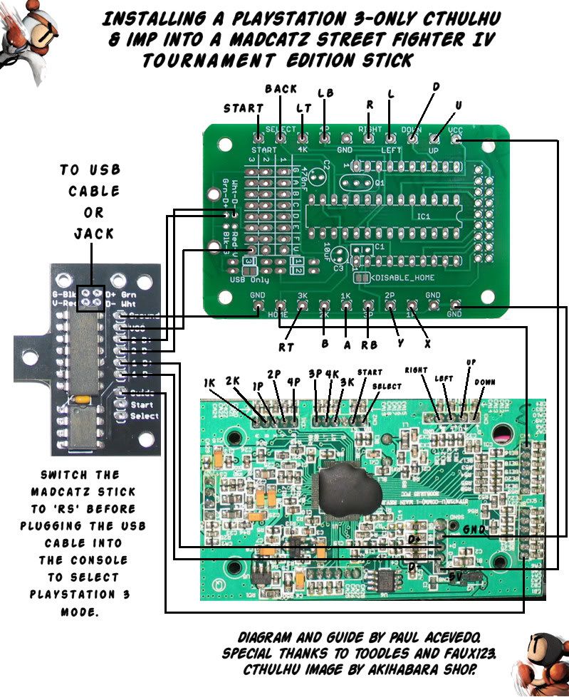
I installed a PS3 only Cthulu and imp by only taking off the top panel. I can’t offer any MC Cthulu help, but I can tell you that if you follow Bomberman’s guide, you don’t hold a button to switch consoles - you just change the LS-DP-RS switch to select your console. LS and DP are the primary, while RS is the secondary.
Forgive the noob question, but when Bomberman said that we can solder each wire to the under side of the PCB, what exactly does that mean? Putting the wire through it’s appropriate whole in the PCB and soldering to edge on the underside??
Which step are you talking about? There aren’t any holes in the TE/SE PCBs. But all the soldering points are on the bottom of the PCBs, not their tops. One glance at the PCBs would tell you that, and the guide has plenty of pics of them too. (But the Cthulhu soldering points do have holes, so feel free to put wires through them.)
i agree it’s pretty weak that this didn’t keep sticky status when they were re-evaluating the threads. so many people have questions about this stuff, and it’s all laid out perfectly hear… bad decision imo
I’ve been subscribed to this thread for so long cause I always referred to it when thinking about/actually modding my stick. They really should resticky it o_o
I think what you’re asking is “Can I solder to a point on the bottom of the pcb?” Answer - yes. You can solder to a point either on the top or bottom of the TE/SE/imp/Cthulhu pcbs. I myself got lazy and soldered to points on both the top and bottom of the Cthulhu pcb o_o
Please forgive me, ive searched now for an hour with google and the forumsearch and i havent found my answer c.c… So, i had used my TE just for SF4 on the PC, and i will get a pretty cheap PS3 the next days, i also already have an preassembled Cthulhu v.1.3 here.
I got following question, i just want to build the preassembled Cthulhu into my stick, no IMP, nothing fancy, since i just play on PC/PS3 anyways.
I have just seen diagramms WITH imp, anything i need to be aware of without one? What do i do with the GND and VCC connections? Is that any different? Is there any diagramm which shows the installing without an imp and by just “taking the original cable dead” and doing everything over the Cthulhu?
Im aware that the “answeres are already in here” reply might come, but i truly searched for an hour now without any results, if theres one already, please just give me a link
I’m assuming you’re basically modifying your 360 TE to be a PS3/PC TE - not dualmodding.
Short answer - you will not be using the GND and VCC connections which go to the imp that are shown in the diagrams. Why? Because since you’re not dualmodding, you don’t need those additional connections. Aside from the button leads (1p, 1k, etc), the only leads you will be using are the four on the bottom (D+, D-, V, G).
All you really have to do is cut the USB cable already inside your 360 TE and wire it up to the Cthulhu. The colors are the same for most USB cables (including the one in TEs), so it’s pretty simple to do.
Doh! I havent really thought of that, however, my cthulhu is already preassembled, which means that there is a quite solid usb-jack soldered on. So it would be the easiest to unsolder it and just soldier the usb cable already inside onto it? Which color goes to where? xD
And thank you alot for your quick reply, youre a great help ^^
[details=Spoiler]You know, I could be wrong about this, but I don’t think you even have to desolder the jack - just take note of which leads are what, then turn the board upside down and use the leads on the bottom. Again, I could be wrong, but I don’t see why you couldn’t do that. I could see issues occurring if you had a cable plugged in at the same time, but I don’t see that happening since it’s going to stay inside the stick. **Someone please correct me if am wrong.
**
Anyway, if you decide desolder the jack (I’m the type of person to try something unless I see a logical reason not to), it might be easier to work with (more room and surface area to solder).
If you’re worried about ruining your 360 TE cable and don’t want to cut it, don’t worry about it. If you cut it, you can always resolder it back on. Even if the cable broke, you would just need to get a new USB cable and solder it on - the TE is quite easy to mod and work with in many ways.
[/details]
The easier/shorter way - wire up the buttons and just use a new USB cable. No soldering required at all. However, since I don’t have my TE on me, I don’t know if you can fit another USB cable through the hole that’s already made for the existing cable. If you can, just do this. If not, consider resoldering your 360 cable to the Cthulhu.
The diagrams need updating. Since all cthulhus now have the diodes and USB jack installed, trying to solder to the points listed is a bad idea. The D- is anywhere in column D, D+ is column E, and any G column will work for ground, and any V column will work for incoming power (from the Imp. Power between cthulhu and 360 should come from teh VCC screw terminal or unlabelled hole).
Ok, got it - thanks Toodles. If you’re not going to use your own USB cable, solder the 360 cable to the points listed here. Again,
D- : white
D+: green
G : black
V : red

