First remove the metal plate from the bottom of the stick by unscrewing all 6 Philips screws.
Installing 24 mm Start and Back buttons
If you are going to install 24 mm buttons, drill the holes now, using the outer edges of the old button holes as guides. Be careful to allow enough space between the new holes so that the buttons will fit next to each other. Afterward, Dremel away as much excess plastic inside the stick as needed to allow the buttons to go all the way in.
Installing the RJ-45 jack
Now let’s drill a hole for the RJ-45 jack. For a TE stick, refer to this post.
First observe where we will be mounting the Cthulhu board.

We want the RJ-45 jack far enough out of the way that it won’t interfere with the Cthulhu’s mounting position.
After drilling the main hole, Dremel away the excess plastic inside the stick that would keep the jack from mounting flush inside the stick.
Now remove the black piece of plastic with the Neutrik logo from the RJ-45 jack. Hold it over the outside of the hole you just drilled and use the two smaller holes in the plastic as guides to drill screw holes.
Inside the stick housing, slide the rest of the RJ-45 jack into its 24mm hole. Then place the black plastic piece on the outside and screw it in.
Soldering diagrams
Here is a map of where we will be soldering wires to the Xbox 360 PCB. You can solder every single wire to the underside of the main PCB.
For the Cthulhu board, Akihabara Shop’s excellent diagram will do the trick. http://akihabarashop.jp/misc/Cthulhu.jpg
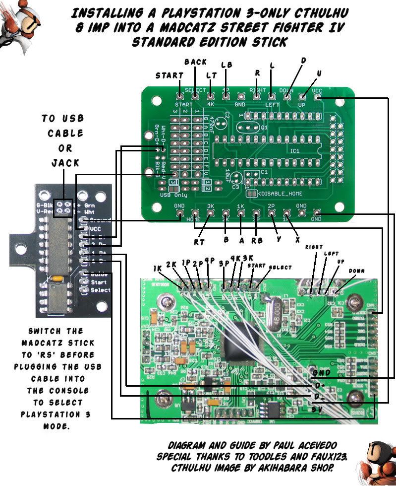
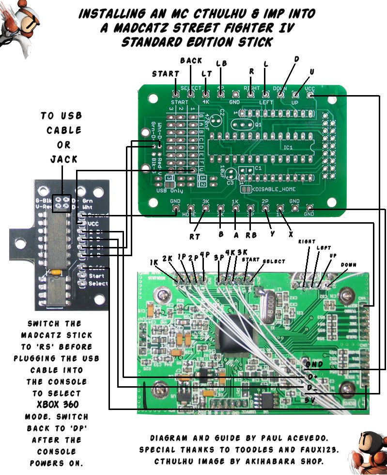
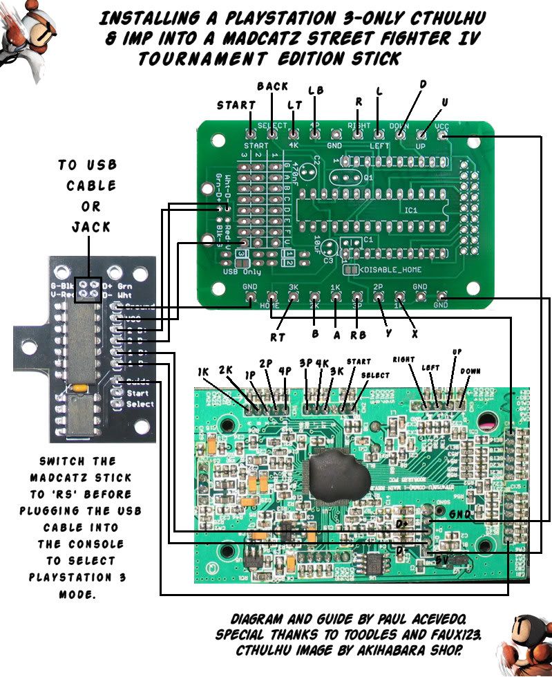
Update! These images show where every wire should be connected between the PCBs.
PS3-only Cthulhu to SE Stick
MC Cthulhu to SE Stick
PS3-only Cthulhu to TE Stick
MC Cthulhu to TE Stick
Please note that with PS3-only Cthulhu mods, the diagrams show the power wire connecting the Cthulhu and Imp as coming from the 3rd row V point. You should actually connect the wire to the Cthulhu’s USB 5V point, not row 3-V.
Assembling the Cthulhu and Imp boards
Each of these boards come with several chips and such that must be soldered on. Refer to the printed instructions they come with. Make sure you install every component - including the capacitors - before mounting the boards.
Mounting the PCBs
Unscrew the SE stick’s main PCB. Remove the USB cable by either desoldering it or cutting off the wires as close to the SE PCB as possible. Cut the wire that was attached to SGND (shielded ground) completely off because we won’t be using it when attaching the cable to the Imp. Flip the SE PCB over and screw it back in. Now remove the right-most screw from the buttons quick disconnect panel and mount the Imp board where that screw goes. Replace the screw. The arrow in this image shows which screw I am referring to.
Mounting the Cthulhu board is slightly trickier because it will rest directly over the SE stick’s Guide/Turbo panel PCB. To prevent the two boards from shorting each other out, put something nonconductive like a piece of cardboard or an index card between them. You can use electrical tape as well, but it’s not thick enough to use all by itself. Remove the 2 screws in this picture and line up the MC Cthulhu over their holes. You need to replace the left-most screw with a longer one.
Wiring from the SE PCB to the Cthulhu
You have decided on what button you’ll be connecting each Playstation 3 button to, right? The scheme I used is A - X, B - Circle, X - Square, Y - Triangle, Left Bumper - L1, Left Trigger - L2, Right Bumper - R1, Right Trigger - R2, Back - Select, Start - Start, and Guide - Home. Solder a wire from each of these points on the SE PCB to the matching spot on the Cthulhu. You can also use this spot on the Turbo/Guide PCB for the Guide button, but only if you attached a wire there before mounting the Cthulhu.
Connect all four directions from the SE PCB to the appropriate spots on the Cthulhu as well.
Now connect a wire from one of the Cthulhu’s ground points to any of the SE’s ground points. Do the same from the 5V point on the Cthulhu to the VCC point on the SE PCB.
Note: If using a presassembled Cthulhu or MC Cthulhu, the wire terminals won’t work with Kynar wire. You could desolder the terminals, but it’s much easier to just solder the wires from the 360 PCB to the points beneath the terminals on the bottom of the Cthulhu board.
Wiring from SE and Cthulhu PCBs to the Imp
Let’s install the SE’s USB cable to the Imp. The imp has four holes specifically for the USB cable at its top, so make sure you attach the USB cable wires to those exact holes. Solder the cable’s green wire to D+, white to D-, red to V, and black to G. We’re not using the shielded ground wire, so hopefully you cut that off already.
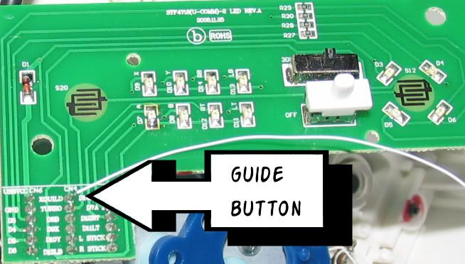
Connect the SE PCB’s GND point (the one where the USB cable was originally attached, for simplicity’s sake) to the Ground points on the Imp. Run a wire from the SE’s Guide button point (which should already have a wire attached to it unless you opted to use this alternate point to connect Guide and Home) to the Guide point on the Imp. Ignore the Start and Back points on the Imp; we won’t be using them.
The Imp still needs a power wire. If using an MC Cthulhu, run a wire from the V point in the first column on the MC Cthulhu (right above Column 2, where we’ll be connecting the RJ-45 jack soon). The point is labeled at the bottom of this image:
If using a PS3-only Cthulhu, run the power wire from the Cthulhu’s USB 5V point (next to D+ and D-).
If you are installing an MC Cthulhu rather than a PS3-only Cthulhu, connect the 360 SE PCB’s D+ and D- points to the Imp’s 2D+ and 2D- points. The MC Cthulhu’s D+ and D- wires should connect to the Imp’s 1D+ and 1D- points.
However, if you installed a PS3-only Cthulhu, feel free to connect the 360 data wires to the Imp’s 1-data points and the Cthulhu’s data wires to the Imp’s 2-data points. The Imp will switch to whichever console’s data wires are connected to the 1-data points by default. You must hold the Guide/Home button when inserting the stick’s USB cable into the console in order to switch to the system that is wired to the Imp’s 2-data points. Does that make sense?
**
Note: **If using a presassembled Cthulhu or MC Cthulhu, the USB jack covers up the Cthulhu’s 4 USB solder points. There’s no need to remove the jack; just solder to the corresponding points where the jack is attached beneath the Cthulhu board.
Your Cthulhu should now look a lot like this:
And the SE PCB and Imp should look like this:
Testing the Stick, Round One!
At last your stick should be ready to test! I prefer to test them with a Windows PC since you won’t have to worry about turning your consoles on and off or booting games.
First test the Cthulhu by simply plugging it into the PC and then going to Control Panel/Game Controllers. An MC Cthulhu will come up as “Cthulhu Multiconsole Edition”. Apparently Windows may not detect it properly until the second time you plug it in, so remove and reinsert the USB cable if it doesn’t show up as a Cthulhu. From the Game Controllers Window, highlight the stick’s name and click on Properties. Verify that every single button (including Home, excluding Turbo) and direction functions correctly. Buttons 11 and 12 are unused, so don’t worry about those two.
To test the Xbox 360 portion of the stick, hold Guide when plugging the stick into the PC. The Guide button will light up when the stick is in Xbox 360 mode. Windows should see it as “Arcade Stick (Street Fighter IV FightStick)”. Make sure every single button works, except for Guide and Turbo, which have no Windows functions.
Wiring the RJ-45 jack
Hopefully your stick is functioning correctly in Xbox 360 and Playstation 3 modes and you are ready to add support for extra consoles. Cut off one end of your ethernet cable so that only 6 inches remain attached. Using an exacto knife, slice from the cut end all the way to the remaining RJ-45 plug. Chop off the rubber shielding so that it doesn’t interfere with the wires you’ll be soldering.
First you must determine which wire goes to which pin on the RJ-45 connector. Use AcceptableRisk’s image to number the pins. There are two ways to determine which wire goes to which pin:
Visually: Look at what color wire is connected to each pin and write it down.
**
Multimeter:** Set the multimeter to continuity test. Hold one lead to pin 1 and then hold the other lead to each wire until you find the wire that corresponds to the pin. Repeat for each pin, writing down which color wire goes to which pin. The multimeter method is a little more accurate since wire colors may be obscured inside the actual RJ-45 connector.
Now it’s time to wire the ethernet cable to the MC Cthulhu. The MC Cthulhu has 3 rows of solder points dedicated to adding extra cables; each row is labeled G, A, B, C, D, E, F, and V. You can connect your Cat5 cable wires to either the first or second row. I used the first row but the second would actually give you a little more room to work with, so use that instead.
Attach the ethernet cable’s wires like so:
**
Pin 1: G
Pin 2: A
Pin 3: B
Pin 4: C
Pin 5: D
Pin 6: E
Pin 7: F
Pin 8: V**
Finally, plug the RJ-45 connector of the cable into the RJ-45 jack inside the stick.
Congratulations, your arcade stick is complete!
But our princess is in another castle… Err, you still need some cables to plug in that RJ-45 jack.
Creating cables for other consoles
Coming soon!


