That doesn’t sound like why your stick wouldn’t work, try making sure that the exposed wire is in the teeth yes. Insulation is a no-no.
Doing that as we speak. Tried plugging in a USB cable right into the Cthulhu and I got a “Windows does not recognize this device” malfunction, which shows power, but a cabling issue. So going to fix all that cables going into the cthulhu assembly. It’s probably just not being grounded/powered properly.
Metal-to-metal contact only.
26AWG is fine.
Nothing, no juice, no lights.
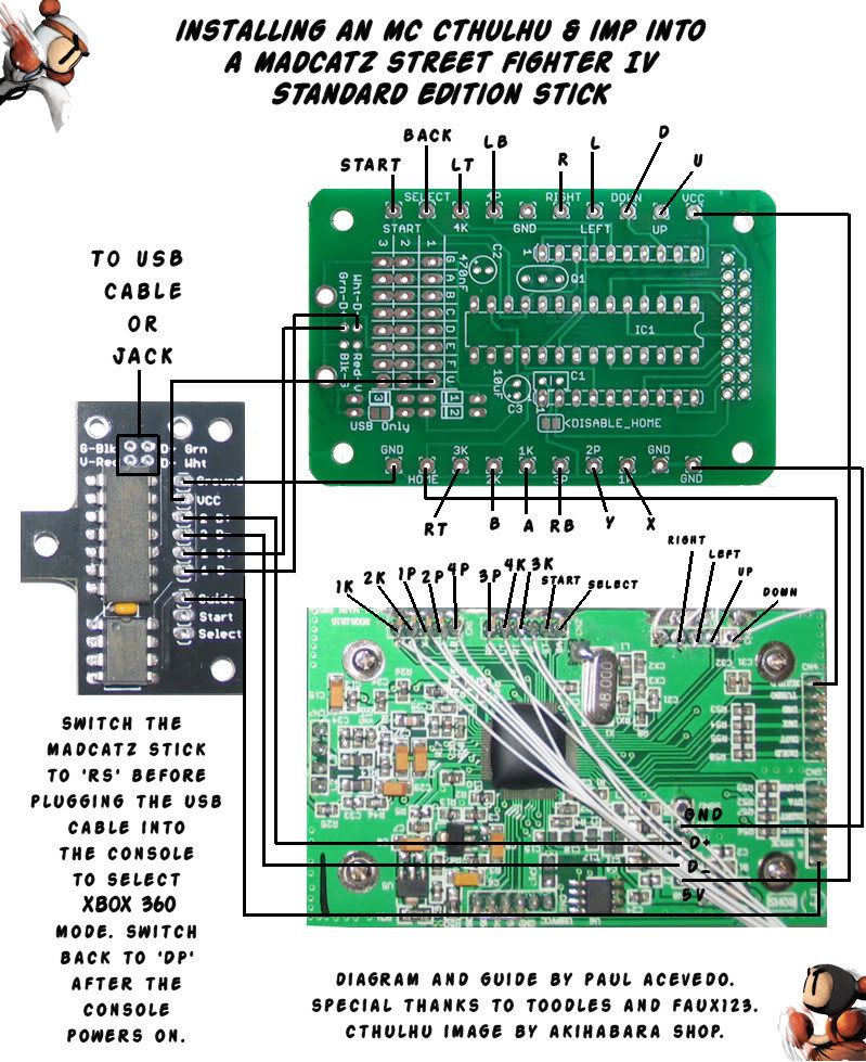
Reconnected and restripped the wires going into the Cthulhu assembly. Followed the diagram here. http://i65.photobucket.com/albums/h201/eastx/arcade%20sticks/mccthulhuandimptosestickdiagram.jpg
Notice the strange indescrepancies between the picture itself and what it wants me to do. The picture shows cables attached to ground points it doesn’t want me to do. I did everything from point to point as that diagram states. I have the ground from the SE going to the bottomright assembly point on the Cthulhu, as it says in the diagram, with the bottom left ground going to the Imp ground, as it shows in the diagram as well.
VCC is going from SE up to the Cthulhu’s upper right point as said in the dragram, with the Imp going to Row 1 of “V” column on the Cthulhu. USB is connected properly to the Imp board. Closest thing I can see as a similar problem on this thread is this post:
http://forums.shoryuken.com/showpost.php?p=6557193&postcount=75
http://forums.shoryuken.com/showpost.php?p=6560850&postcount=79
Toodles responded with this:
This does not make any sense to me, because as per Bombermans diagram, there is already a cable going into the VCC screw terminal (The 5v point from the SE is going there)
So unless the diagram is wrong, how is My Imp going from Imp VCC to Row 1 “V” column “Not connecting it to the proper VCC that powers the boards?”? Is the diagram wrong?
Edit: If I can’t get a solution by tomorrow I’ll just desolder everything and go according to Faux’s diagram instead of Bomberman’s. It seems to have the highest success rate in this thread, though I liked the idea of switching boards using the switch instead of the home button. If Faux’s works, I highly suggest looking at that Diagram again. Something doesn’t make sense. Specifically the lack of using grounds on the SE in comparison to Faux’s. It just looks so dramatically different in the way it’s wired.
Just throwing this out there to be sure we’re on the same page. USB cable goes to the Imp, VCC from the Imp goes to row 1 column V, and the VCC connection between cthulhu and SE pcb goes from the VCC screw terminal to the VCC of the board (labelled either USBVCC or +5v on the SE pcb).
I also want confirmation that the assembled MC board has the four diodes (either two glass and two black, or four black if its a newer board) present on it.
If that’s the case, grab a multimeter, slide the switch over so it should go into Cthulhu mode, and start working through the troubleshooting guide in the cthulhu thread (its linked in the first post). It’ll have you checking voltages and stuff at various points. Let me know how far you get.
Inverse can you post some pics of your mod, it really helps to have something to look at. Close up pics of all 3 boards.
You know what, I’m not too sure if those diodes are on there. Where are they supposed to be? I’ll upload a picture of it in one moment, since apparently I may not have a fully built MC after all. There’s nothing red or that looks like glass to me.
I do not have those diodes in the picture. (Pic from the instructable)

They did not come with my assembled Cthulhu.
… Were they supposed to?! If so where am I supposed to get them now? The diodes aren’t even listed in the Kit list on the sheet that came with it. This is the first time I’ve even heard of them. I knew I should have gotten a disassembled Cthulhu. LoL
At least the spot over USB only is jumped by a small blob of solder. But that’s it, no diodes in place or in the packaging. Which tells me this was originally a PS3 only kit, just assembled fully assembled Cthulhu. Which is why the sheet doesn’t have the diodes listed. So I’m to assume this is not an MC Cthulhu. Looks like I might have messed up in purchasing or was sent the wrong thing. Whatever. I’m going to recheck everything now since I apparently built this with the assumption it was the wrong kind of Cthulhu.
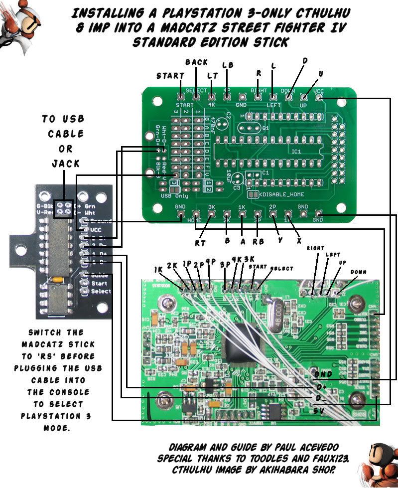
Edit: Well the only difference in the Diagram for PS3 Cthulhu is power from the imp is going to Row 3 on the “V” column. Should I resolder it to this position? (currently at Row1) Everything else is the same as the MC Cthulhu except for master/slave positions, but I already made the 360 Master and MC Slave. So I already am close to the Diagram for the PS3 only setup. Seems the the spot over “USB-Only” is already jumped. Going to start trouble shooting with the multimeter.
Hello, I just had a quick question. I just got a sanwa flash joystick. It must be powered. Where would I draw power from in this dual pcb set up?
VCC screw terminal on the cthulhu
Inverse: you have the PS3 cluthu. If you want to make it work connect your 5v to ONE of the red points below.

Excellent, rewiring the VCC from “V” columns, to the
http://img22.imageshack.us/img22/4475/vcc.jpg
on the card and I got power to the SE which is D1 on the Imp.
Getting a “USB not recognized” when trying to boot to the Cthulhu (after switching to RS). I’m close though, I can smell success around the corner. Going to read the rest on the thread looking for this particular issue.
Edit: Plugged a USB cord straight into the Cthulhu, works perfectly with that. So I wouldn’t be wrong in assuming the problem is related to a wiring problem on the imp itself?
D2 + (Imp) is wired to D - Row 1 (On Cthulhu)
D2 -(Imp) is wired to E - Row 1 (On Cthulhu)
(I have a feeling you guys are going to LoL and tell me I have them backwards.)
Edit 2:
[Quote=Toodles]
Q: Where can I access the D+/D- lines for a dual mod?
A: D- (white) can be tapped in the D column. D+ (green) can be tapped in the E column.
[/Quote]
Fuck, I did. Goddamit. Feel free to ignore me now. I’m done.  Thanks for the help guys.
thanks toodles, I should be hitting you up after evo for the trade details.
EJM: still want that mod done , hopefully get that stuff out to you in the next week or two. Sorry for the delay. Funds are a bit tight at the mo…
Let’s say I am taking my SE pcb and using that for a custom with a cthulhu. Am I just able to re-wire the guide button? I don’t care for the turbo function in the slightest, but I would also need the DP/LS/RS change capability too I suppose.
Would anyone have any ideas?
Yes Ailerus, you can use the Guide button point on the main SE PCB or the one from the Guide/Turbo daughterboard. Not sure what the best way to retain the 3-way switch is.
BTW do you still need the actual Turbo/guide panel (the white plastic piece, not the switches or the daughterboard PCB)? I could use it if ya don’t.
The Guide button can be hooked up to any button you want; just connect the XGUIDE point and ground to a button.
For the LS/DP/RS, you dont really need it. If you just don’t hook them up, it’ll default to the Dpad. If you absolutely want to hook them up, you can, get a three position SPDT switch. I think that’s the right name for them; they have three tabs on the bottom, the R stick point goes to one side tab, the L stick point goes to the other side tab, and the middle goes to ground. Maybe they’re called ‘On-Off-On’ type. The center pole should connect none of the tabs, while on either side connect the tab to the center tab.
From my limited understanding, no matter what you decide to use, whatever is wired to the “Guide” point on the Imp is what the Imp will use as a switcher.
As long as it’s not wired to another point already I think. You could technically make a button just for it in a custom and wire that to the Guide point on the Imp and it would be your switcher. Though I would just use Guide or one any of the buttons you’re not planning on using in your custom.
Sorry, the reason why I am switching to a custom box with the SE pcb is because the SE’s case and panel were messed up due to a bad paint job. It’s terrible to look at.
did it get messed up past the paint aspect? You could always sand it back down and start over again.
So I installed the mod on a TE stick, plugged it in, and it didn’t work. However, when plugged into the PS3, the LED for some reason lit up quite well.
Afterwards, I tried to hook it up into the 360. It gave me a Red Ring error. I removed it. The Red Ring Error went away.
Anyone know what could be the problem?
Why aren’t you testing this out on a PC? The very first post of the forum shows instructions on testing your work. I find it hard to believe you went through the trouble of soldering all those wires just to suddenly ignore the post that made this thread. LoL