yes, there is 2 soilder point in “usb only” section, soilder them and you should have connectivity on the rest of board’s Vcc point, except rack 1-3. you probably dont need a wire to jumper those point, just get load of soilder and stick them together on those spot, and it will do the job.
So no one knows why just my start button wouldnt be working?
there is a troubleshooting guide at Toddles cthulhu post. go through it if you think is the board issue.
http://forums.shoryuken.com/showpost.php?p=6789666&postcount=1975
I wish I was as lucky as some you guys on this thread.
I have the PS3/PC Cthulhu board and IMP and I tried my hand at modding my 360 SE stick with no luck. It got so bad that I lifted up the solder tin point on the 360 PCB for 5V, and now I can’t solder a wire on it anymore because it has nothing to solder to. Before this I kept going back and forth trying to figure out what I might have done wrong, since nothing was work 360 or PS3. Soldered the GNDs, VCC points correctly and still nothing.
Now I have to find a new 360 SE Stick, swap the boards and return the “new” stick back so I can try again. Unless if someone knows a way to still solder to the 5V point with no tin? Any help would be great. I don’t want to give up and end up buying two new sticks, 360 and PS3, I just want one for both. If anyone needs pictures for reference, let me know.
Thanks.
Non-MC Cthulu users READ ME
Fixed! My problem was REALLY, REALLY simple. The instructions on page 1 are specifically for a MC Cthulu. However, I have a non-MC Cthulu. Therefore, I was trying to pull power from the wrong point on the Cthulu. Instead of using Row 1 (which is not even hot as I have a non-MC), I used point A on the unlabelled row at the back of the Cthulu. Now my imp has power, and everything works GREAT!
there is another 5V solder point on the pcb, just solder it to the pin. look the the first page of this post for diagram.
hopefully the losing tin spot wont stop connectivity continues from the spot and on, i have no idea the effect of the losing tin to the pcb.
I read through that troubleshooting guide but im not sure how to apply that to my problem can you point me in the right direction just a little confused on the troubleshooting page. Not sure where to start.
Check me out. I just got finished installing everything. I love it! This is the first stick I have every owned, been playing on pads for years. It feels great and the cthulhu makes is even better. I didn’t want the spaghetti monster hanging out inside the stick so I used rainbow wire. I also hot glued the Cthulhu down instead of screwing it in.

It also has sanwa buttons/stick and an octo gate though I think I’ll be switching back to the square.
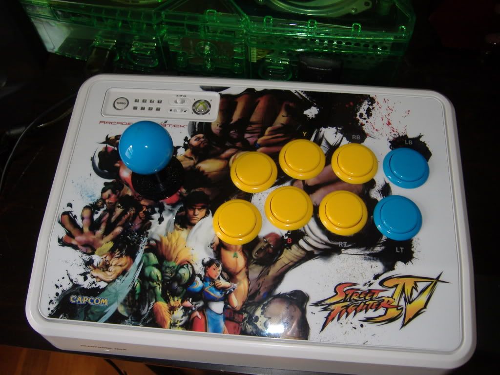
The main reason I got the stick was to play 4 on the 360 but now I’ve been using it more on the original xbox /w all the emu’s. I also made this little usb adapter for the xbox 1 out of a USB swivel adapter I got from radioshack for $1.29 on sale. It’s perfect.

It took me a while to figure out how to get it to recognize the Xbox 1, which BTW if you found my post but still don’t know how, hold left when inserting it into the xbox 1.
I wanna thank
bomberman 4 the tutorial
faux123 4 the great wiring diagram <-- this should be in the tutorial
toodles 4 the cthulhu and imp of course
gamingnow.net 4 the parts and free/quick shipping
Thanks ezpoint, I’ll try that tonight.
i fixed mine cause im a badass like that
question for you
- is the start button work on the xbox 360 or PC as madcatz pcb?
- is the wire connected to the right spot and there is no shorting on both board?
- is you cthulhu pre-assemble?
if yes to the above question, then that mean is the cthulhu’s problem, i would suggest you talk to vendor for replacement, or support.
if #1 = no, that mean there is problem, something is short or malfunction (either madcatz pcb or cthulhu), disconnect the start connection from cthulhu and make sure the madcatz pcb’s functionality. if madcatz pcb work after disconnect from chulhu, that mean problem is with cthulhu, or other way around.
next thing is double check all the solder connection on the cthulhu board, including the PIC, cap, resistor, and button connection, make sure there is pin inside and no shorting. or madcatz’s solder point.
if still cant spot any wrong, take couple close up picture and post it (both cthulhu and madcatz pcb, top and bottom view) on toodles’ offical cthulhu thread and ask for troubleshoot step for individual button.
When you say you “used point A” which one did you choose? The top row or bottom row?
I actually did add the step where I tell you to jumper the #1 diode spot, so the instructions no longer cause problems for a regular Cthulhu… But I need to go back and make it more clear and add a picture, which I can hopefully do soon.
Bomberman,
So is it run a wire from VCC (IMP) to Point A (Cthulhu) AND jumper the #1 diode? This is were I get confused.
Thanks ezpoint for the Help, GO CANADA
You only need to jumper the #1 diode if you run the Imp VCC line to the Row 1 Column V point. If you connect it to the unlabelled point A on the cthulhu, you don’t have to do the jumper.
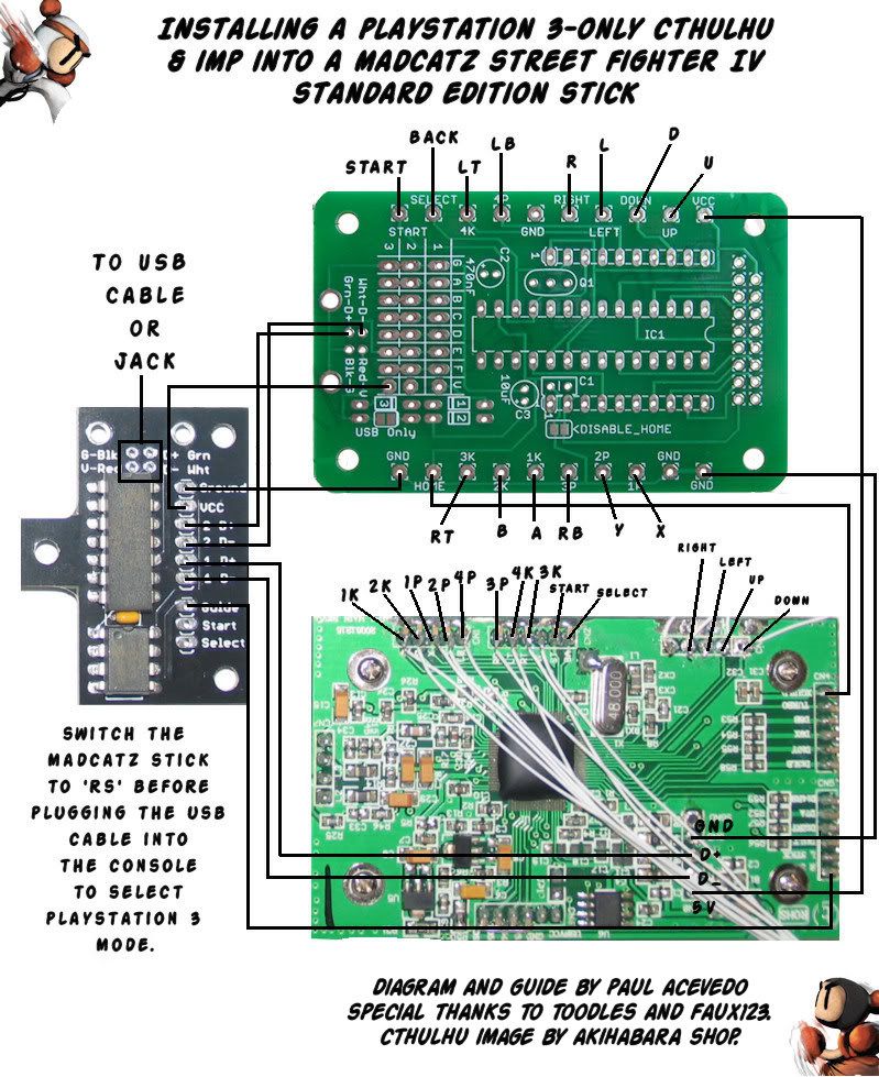
http://i65.photobucket.com/albums/h201/eastx/arcade%20sticks/ps3cthulhuandimptosestickdiagram.jpg
I’ve made images like this for:
PS3-only Cthulhu to SE Stick
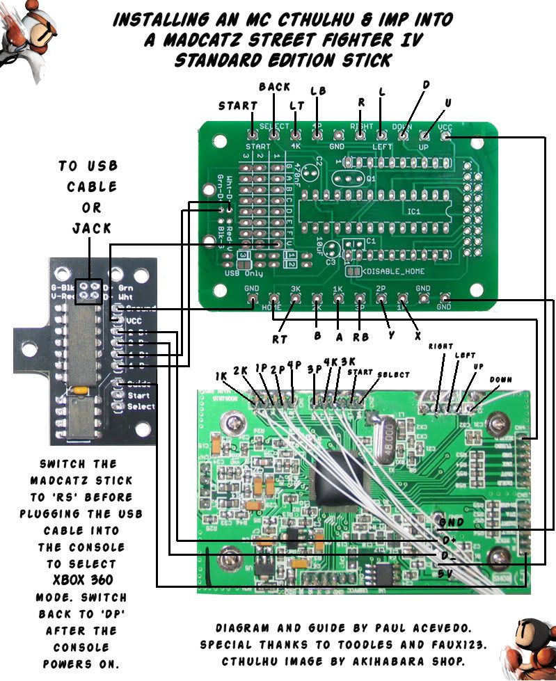
MC Cthulhu to SE Stick
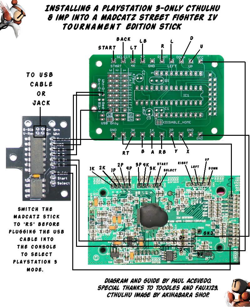
PS3-only Cthulhu to TE Stick
MC Cthulhu to TE Stick
What do you guys think?
The ‘switch back to DP after the console powers on’ is unneeded. The Cthulhu and Imp dont care about that switch at that point.
You might want to check the connection for the Imp’s Guide. While I’d expect it to go to ‘R Stick’ it seems to go all of the way to, umm, can’t tell.
The power from the Imp appears to go to row 3 column V. You might want to make a note there that diode #3 needs a jumper if there isn’t something already there; might also want to move it to 1V instead so it matches what you’ve already written.
Maybe move the Imp<->Cthulhu D+ and D- to the columns (D- = D, D+ = E) so the diagram is the same for assembled as well as kits?
Damn, Im a critical motherfucker. Please dont take it that way; I’m seriously impressed and thankful.
Crap, I had all the lines going to the right places but then I did some repositioning and the layers messed up for some reason. Fixed. And don’t worry, I want to catch all errors and get the guide to be as helpful as possible. I’m thankful for your help.
Can you please elaborate on this suggestion, Toodles?
The diagram you have up has the D+ and D- from the Imp going to the holes used by the USB jack on the Cthulhu. I’m suggesting to instead connect them to one of the holes in the D and E column instead. If the person has an assembled Cthulhu with the USB jack, the holes in the diagram won’t be available. Even if the person has the kit, the drill size of the column holes is larger than the USB jack holes, and the copper pad is larger. Those spots are just much easier to solder to that the USB jack holes, and work on both kits and assembled boards.