The Neutrik jack is going to be mounted from the inside of the case to the back of the storage compartment. If you use the Neutrik plug on the end of your system cable, the compartment door will not close.
I am not disciplined enough to have this going on. I am sure at some point the door will get whacked.
Haven’t drilled anything yet I thought about putting it next to the Select & Start buttons
But all I have is a 1" Hole Saw tool and I think that would be too big
What size do you think will fit next to the Select & start buttons…?
I now have 2 options to think about
I already ordered the NE8FDP-B & the NE8MC-B-1.
1.) Original Look using the Neutrik Jacks jack is just hidden inside of the cable compartment and in order for the cable compartment to close completely I would have to store only the original usb cable and if a RJ-45 cable is connected to the jack I would need to disconnect it and store it elsewhere for the compartment to close completely.
2.) Easy to access jack even though it might not fit next to it and if the hole is too close it runs the risk of cracking over time.
For the Neutrik jack, your only choice is a 24 mm hole saw bit man (unless you remove the Back button and used that hole). Otherwise you would have to choose another RJ-45 jack, for which I can’t provide support.
I would not suggest drilling another hole. The Neutrik jack is deep to begin with. Then you have to attach a cable into it. After I measured, this was not a good solution while using the Neutrik Jack.
The best solution I could figure out was to remove the select/back button and put the RJ45 there. Then reroute the turbo button so that it acts as a select button. This only adds two screw holes.
I see what you mean now by how deep it is damn was planning to go that route.
I guess using the select button and rerouting it to the Turbo button but what about
the Select & Start mod along with the lock option how would that interfere
I need a little help with connecting the USB cable in my Cthulu/Imp setup. I have a pre-assembled Cthulu, which includes a soldered USB connector. The section I quoted above shows that I need to use the data points from my Cthulu to connect to my Imp. Would the easiest way to do this be to de-solder the USB port and do away with it? Otherwise, it seems as though I would need to connect a USB cable, then splice the cable to make the connection to the imp. Is this correct? If so, which option is the “best?” It seems like getting rid of the USB port is the way to go. However, I’d like some advice before I de-solder the puppy. THANKS!
Looking at the section to the right of the start button doesnt look like the RJ-45 would fit next to it considering how deep it is it would hit the screw hole for the case and the cable compartment doesnt look like a good idea either
so if I were to use the Select button how would I reroute the turbo …?
SurfKahuna you don’t actually have to remove the USB jack. You can solder your wires under the Cthulhu board at the points that the USB jack connects to. This is slightly easier, but removing the jack is fine too.
Yes Maven, running a wire from the Back button point on the 360 PCB to the Turbo button’s soldering point, and then cutting the wire that goes from Turbo to the 360 PCB would turn the Turbo button into Back/Select.
Hi RemzRR,
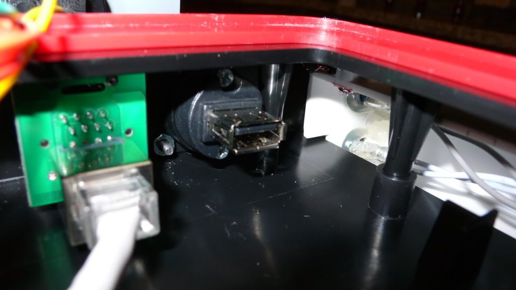
I just added a Neutrik RJ-45 jack to my case and I used a 24mm hole saw. The hole it cut actually was a little bit bigger than 24mm. If you use a 25mm and it also turns out to be a little imprecise it could be too big. That would show when you mount the Neutrik jack with its bezel on the outside (hole would be too big). You could still mount it with the bezel inside then it is just centered in a slightly larger hole.
You also need to drill 2 holes for the mounting screws and they are really close to the center hole. Maybe better use a 24mm hole saw or use glue to fix the jack. I attached a picture (sorry for the poor quality, it was the only one I could dig out quickly that shows the holes).
HomeDepot and Lowe’s don’t sell 24 mm hole saw bits. Like I say in the first post of this thread, Ace Hardware is one of the few places you can find them.
It has 25mm and 30mm bits, but remember, you get what you pay for. For buttons, I know 25mm works fine, but you might have a problem with this. I’m not quite sure.
Rock on man! Thanks for the quick response! The only other question I have now before I begin my final wiring session is the following:
Which type of soldering iron is best? The solder points to make seem delicate to the main PCB. As such, would a 25-watt iron be too much? I can vary the heat on my soldering iron, so I may turn down the heat a bit. Also, do you guys use a heatsink when soldering to the PCB?
Personally, I don’t use a heatsink, but I only have a 15 watt iron. $9 at radio shack
Basically, you need a soldering iron with a “pencil tip” (I dunno if that’s the right term, but it has to have a small tip). If you have that, you’ll be golden. It’s really not as hard as people make it out to be sometimes.
Wow, my turnaround time is horrible. Finally took some more pics, and I also figured out that if you take the rubber part of the neutrik boot off, you can still have an internal mount and close the lid of the storage compartment.
You can use either the ‘LS’ or ‘RS’ signal lines on the TE/SE connected to the Imp’s ‘guide’ point, so the slide switch will control which board is used, instead of holding a button down with one hand and using the other to plug in.
I havent tested this personally, but it should work awesome.
Damn that sounds great will these jacks work
NE8FDP-B & the NE8MC-B-1
I already ordered them and did you drill a 24mm size hole inside of the cable compartment. Any issues so far…?
Damn glad i havent started wiring yet woow
Can anybody put out an updated wiring diagram
Lock Select & Start & Turbo along with the top slider button used to select systems
this would be great