If it’s already wired, could you please post a picture of the HRAP board with its soldering points? I was looking for a diagram of the PCB before and couldn’t find one. I need me a HRAP2 because of the heavy base and Seimitsu compatibility. The common ground PCB would just make it all the better.
Hi! I asked this on the other thread, but the people seem to be different in both threads, so I’ll ask here. Why a MadCatz (which aren’t available here at all) is actually easier to work with than with a MS 360 wired pad PCB? Those sticks can’t be bought online, so I would have to ask someone to buy it for me, and shp it to me from there, which might end up being more expensive than buying a used 360 MS wired pad here.
Heh, it wasn’t my intention to fork that thread. I was just trying to break it down for noobs like myself. The problem with your used MS pad is that it may or may not be common ground. If it’s not common ground then you can’t (without major modifications) use it in a dual PCB stick. If you have a local GameStop see if you can pick up one of these. I live in a small town and my store had plenty of them the last time I was there.
I don’t even live in USA, no Gamestops in here, that’s why I was saying that.
Followed this tut to a tee and my pelican universal is now playable on my 360. Thanks Kyle.
I didn’t actually take out the original hori PCB, just solered onto the common ground points of the actual sanwa stick pcb.
how do i leave in the hrap2 pcb and add in a 360 pcb
what do you mean “how” ? just use the harap2 pcb as if it were a controller pcb and do what the 1st post tells you to do 
Fantastic. Let me know if you have any suggestions for improving it.
This has already been brought up a few times, but I don’t think anyone has made a diagram for the HRAP2 with the soldering points labeled. I’d like to see one of these myself, because that’s the stick I’d buy if I went for a Japanese stick. It apparently takes an LS-32 and the PCB is common ground.
This guide was super helpful, thanks again for posting it! I’ve had my own little adventure linking my stick to both a PS1 Dual Shock (H) and a 2008 MadCatz pad. Lots of helpful advice on **zombie cpt’s thread on hacking triggers**, so read the whole thing to get a complete understanding. Key things I’ve learned that might help others (all courtesy of the extremely knowledgeable and helpful Toodles):
-
If you have the 2008 model Gamestop/Madcatz pad, you will need to invert the current going through the trigger signal line to make it work right (i.e. simply soldering resistors to the trigger line isn’t enough.) One fairly simple method is through an NPN transistor, which Toodles details on that thread.
-
If you accidentally completely desolder the pads for the high and/or low lines on the trigger, you’re still OK. The “low” pad is really just the common ground for the PCB, and the “high” pad is really just the +5V line. You can solder your transistor set-up to any other common ground/+5V point that is convenient should the need arise.
-
If you accidentally desolder the “wiper” or center pad of the trigger, you can just solder to some other connected point. Follow the PCB trace, there is a resistor/diode on the opposite side of the PCB you can solder to if you lose the pad on the back side.
-
If you are using the analog triggers on the 360 and the digital buttons on the PS, you will need to use a diode on the 360’s signal line to prevent the signals from getting crossed. Diodes restrict the flow of current so it can only go in one direction. Solder a diode at some point between the 360 signal line and the terminal strip. Make sure the cathode (the striped end) is pointing towards the terminal strip. Current will be restricted to only flow from the anode (the other end) to the cathode. It’s important that it is a low forward-voltage diode. Item # **276-1141** worked for me - it is rated at a forward voltage (FV) of 0.9V. Higher voltages (e.g. 1.6V) appear to resist the current too much and will prevent the trigger from operating on the 360.
Again, fantastic guide, this is a great resource for all stickbuilders!
thanks,
would it be easier to leave hrap2 pcb in and do a dual or just ripping harp2 pcb 2 out .
also is it possible to use mic on controller 2 so i can just use pad for talking or do people drill hole for mic input ?
From what I’ve seen people leave the HRAP PCB intact. Like I said, it would be nice if someone would help out with the ‘connect the dots’ aspect of getting it going.
I have my mic extension coming out the same hole as the controller cable. It’s probably not the best solution. I was just more comfortable doing that then drilling into the case.
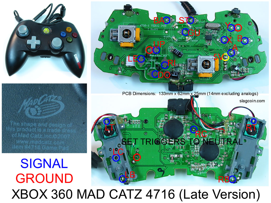
Alright all these diagrams have been extremely helpful. Right now a co-worker and I are trying to mod his custom FINKLE PSX stick and turn it simply into a 360 pad. When looking at these diagrams it seems pretty straight forward to re-solder all the points but there are just a few things I am unclear on. He broke-off the joystick assemblys for the triggers so we now have 3 little contact points on each corner. What do we need to do with these points to simply keep them in a “NEUTRAL” position as all the pictures say. Are they already seen as in a neutral state or do we need to solder the 3 points together or something? Here is a picture of our exact board which is the madcatz arcade joystick 2006.

Thanks in advance. I am assuming we can just map the right and left bumpers rather than use the right and left triggers right?
If you are referring to the little tabs on the bumpers then they’re fine to remove. You won’t have to do anything extra. And yes, you can just use the bumpers instead of the triggers. It will still give you six buttons with ABXY LB RB.
Ty for confirming that for us! As you can see from my sweet paint highlights, the red boxes are where the trigger assembly used to be and the green boxes are the contacts for the trigger. Do we need to solder anything on those contacts to make them neutral or are they neutral like that?

anyone tried to do this on a t5 (tekken 5) hori stick? I modded mine with a true sanwa but really want to keep it for sf4. I’ll probably replace the buttons as well if I mod it for 360 play. The guts are pretty goofy, you have to do some non-orthodox stuff to get it working.
edit: see here http://forums.shoryuken.com/showthread.php?t=131221 I followed this tutorial to mod the t5 based on a suggestion from someone else. I had to scrape the pcb of the stick, so I figure I’ll have to reorder one of those to do this.
edit edit: I’m thinking now it’ll just be best to gut the whole thing and start from scratch using the case of the stick. If anyone thinks otherwise please tell me because it would save me some work
I am attempting one of these in the near future and have a quick question that I don’t think has been answered in this thread at all.
It it possible to remove the triggers from the PSone controller without adding resistors? I know you need resistors when doing this on the madcatz controller, but I was under the impression that that was because those triggers are analog, where as the psone triggers are digital (i think, correct me if Im wrong). Does anyone have any info on this?
Hey… I’m looking through this thread. Admittedly, I’m not reading every last word from every post, but I am trying to read before making an idiot of myself. That being said, I have a few questions.
Question 1: I’m using the MadCatz Retro stick PCB… and… I don’t know how to get rid of the stick caps… as well as the LT and RT boxes… without risking damage to the board. Can you give me the quick “just do this” explanation?
Question 2: I removed this… but thought I’d add it back in. The diagram for the Retro PCB says to set triggers to neutral. I’m reading about this here… but the specifics seem to be about the MadCatz gamepad… do you have specific instructions for the Retro PCB?
Wait. What? I’m currently planning on using the Mayflash Fighting Stick PCB (the PS2/PS3 one). Why doesn’t it work with a dual-PCB mod? Sitting here… trying to reason through it… I can’t come up with anything off the top of my head… but I’m not a circuit guy by nature.
Forgive me if these questions were already explained in this thread and I missed them. Thanks!
Sorry for the late reply. I hadn’t seen these last few posts. 
I’m about 90% sure that you have to add resistors if you remove them. I could dig for the thread where this was said, but I’m confident enough with this answer.
-
I looked at my Arcade PCB. You nudge the analog nubs left and right until they come off. I wouldn’t worry about breaking them. I’ve played with a few of these and have yet to break one. On the PS1 PCB you need to wiggle them up and down.
-
This was originally geared toward the Retro PCB. People were complaining about their availability so I revised it for a pad that people could easily buy. If you leave the triggers intact there’s nothing you have to do. ABXY LB RB will get you six buttons. If you want to use the triggers then you’ll have to add resistors. That’s covered pretty thoroughly on some other posts.
-
Sounds like the Mayflash PCB isn’t common ground. In that case you’ll need to use a PS1 PCB instead.
Thanks for the response. I’ll get my PCB cleaned up now. :tup:
I do wanna go eight buttons. Didn’t know if there was anything special to keep in mind when working on the Retro PCB. I’ll follow the general rules on adding resistors then.
I was under the impression that the Mayflash PCB is common ground, so I’ll have to check into that. Thought that there might have been some other reason to drop it. Thanks for the pointer, though.