Thank you, you answered my question. Just to be clear, I just wanted to know if it’s possible and easy to use a wired 360 pads PCB and make a custom stick.
Oh ya, what size of gauge wire should I buy if I wanna use a wired 360 PCB and Happ parts including cherry switches? does it matter or is it all the same standard size?
Kyle I couldn’t tell from your first post or not, but do you have 2 wires coming out from this joystick (xbox360 and psx wires) to plug into the corresponding system, or did you get em working from 1 wire somehow?
*Edit, the post I quoted got deleted so this looks weird out of context. He asked if the PSX PCB was 5 or 3.3v.
People smarter than I am declared that over in this thread. I’d take your technical questions there since I’m no electronics guru. I was just trying to make this easily digestible for noobs like myself.
I wired up my stick twice using these instructions and have had no problems either time. I originally did it with the Mad Catz Arcade stick and then used a Mad Catz Gamestop pad.
Haha. Therein lies the problem with this thread. I can explain anything that I did in the first post but not much beyond that. If someone asks a technical question I end up deferring to Toodles or one of the other resident geniuses.
If you opt for PS3 instead of PS2 you can do both with a switch. I’ve seen a few sticks done like that. My problem was that I needed PS2 support for the PS2 (obviously), Xbox and Dreamcast compatibility. That may not be a concern if you’re only playing on new consoles.
Have you guys ever come across a buttons circuit working oppositely?
For reference, my mod is a madcatz 360 pcb into a Hori RAP-1
What happened was that while I was testing everything, something happened, which i’m guessing is that the polarity of one of my buttons got reversed. What the button circuit does is that it’s on an always on state like the buttons being held down without letting go. Pretty much the same thing that happens when you engage one of those program switches on the top left of the stick. I tried messing with the program switch that belongs to that button, but the only thing I can manage to do is turn it completely off, or I can have button on/off/on/off flickering.
Have any of you come across this? Or have any ideas as to how I can get it working again. Just to note, this happens when I hook up either of the two pcb’s
I know I can simply map it to a different buttons circuit (which is how I have it working now), but it’s a PITA to be mapping the button every time you’re gonna play, so I want to try and get it back to default
Description of the symptoms is ok, but there is no description of the system. Pictures, which pcb’s are in it, how did you hack them, which button(s) are experiencing the problem, what the buttons on the pads are mapped (“Strong, which is the triangle on the HRAP board and Y on the gamecube pad”) etc.
I have the HRAP-1, and I was adding the madcatz 360 PCB. The circuit that’s messed up is the square (jab) of the HRAP PCB. I have it setup exactly how akuma001 had it pictured in the previous page.
Just to make sure it’s understood, the problem is not how it’s setup, or wired. The problem is with the HRAP PCB circuitry or programming. When this happened, I un-did the entire mod and completely removed the 360 PCB all together. I connected everything back to how it came from factory on the HRAP to make sure it wasn’t a setup problem, and the button is still stuck “on”. I replaced the button itself and that did not work either. I even removed all of the buttons so nothing was connected to the PCB, and it would still be always “on”.
The only thing I can do to get the circuit to turn “off” is by turning the program switch of that button all the way to the top to always “on”. And also, I can get it to flicker on and off if I set the program switch in the middle position.
Let me know if there’s any specific detail you need to find out
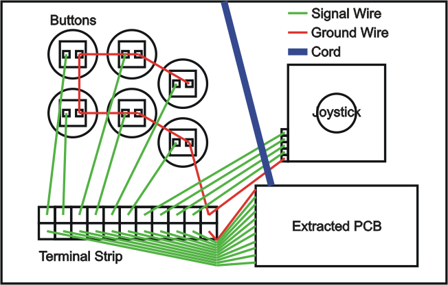
Question… I am modding my Hrap2 SA to do a dual PCB support, but had to replace the original HRAP2 PCB because it shorted out. I am using a PSX PCB and a Madcatz xbox360 PCB to do this. According to the diagram, the ground from the PSX PCB connects to the ground of the Xbox360, which then daisy chains around the buttons, the microswitches for the joystick, and finally the start and select buttons. If you’re not sure which diagram I’m talking about, its this one:
But since my Sanwa JLF stick has a 5-pin connector on it, how do I work the ground wires with that? Should I start wiring the ground from the JLF to all the buttons, then to the xbox360 madcatz PCB ground, then finally to the PSX PCB ground?
I just wanted to make sure that this was okay, as I am not too familiar with how grounded wires work yet.
So from after hooking up the last daisy chained ground wire from a button to the extracted PCB, I can go from PCB ground to PCB ground?
For example: last daisy chained button > ground on XBOX360 PCB > ground on PSX PCB
So basically I would have the same set up as your picture above, but have an extra PCB in there with the wires running into the same terminal strip, and the ground wire running from one extracted PCB to the other, then to the buttons, then finally ending the ground wire at the 5-pin connector on the joystick. Is that correct?
I have the JLF too. Can’t we just bypass the 5-pin connector altogether and use quick disconnects on the 4 joystick directional terminals just like everyone else?
