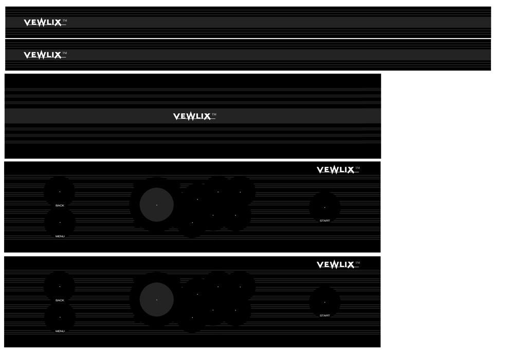
Objective:
‘Enhanced version’
Base Construction:
Materials:
18mm MDF: Front, side, top and bottom panels
40mmx30mm Wood Strip: Cabinet legs
25mmx25mm Wood Strip: Internal supports
Wood Glue: Glueing support strips and panels together
35mmx4mm Wood Screws: Screwing support strips and panels together
40mmx4mm Wood Screws: Screwing cabinet legs to side panels
Cabinet levelling/adjustable feet
Tools:
Jigsaw For rough cutting MDF panels
1/2 inch Router For trimming and bevelling
Flush trim bit For trimming panels to size
Large Chamfer bit For bevelled edges
Drill For screw pilot holes
Screwdriver
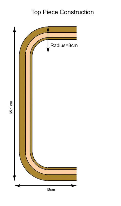
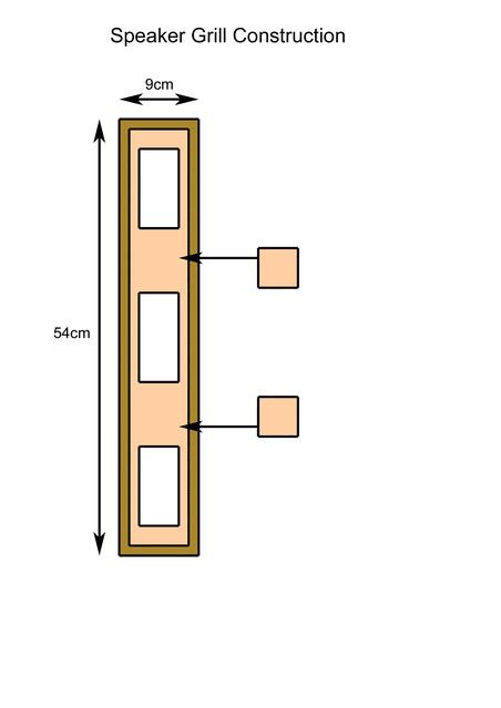
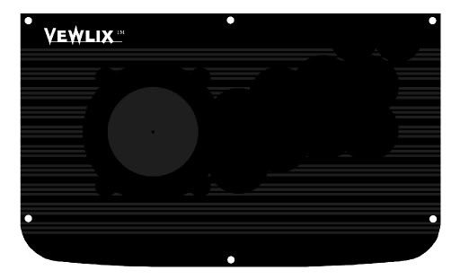
Plans for wood sections/pieces:
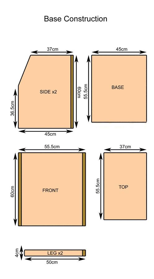
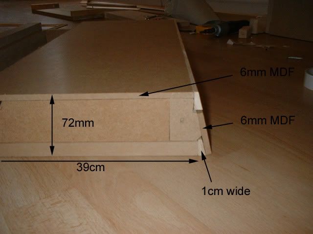
Plan description:
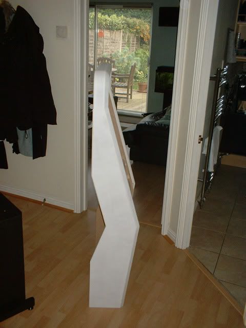
The darker brown areas show where the MDF has been bevelled using the chamfer bit.
The front piece protrudes slightly to allow for the bevelled edges.
The front edges of the side pieces have been bevelled slightly to give the overall appearence a more interesting and less box-like look
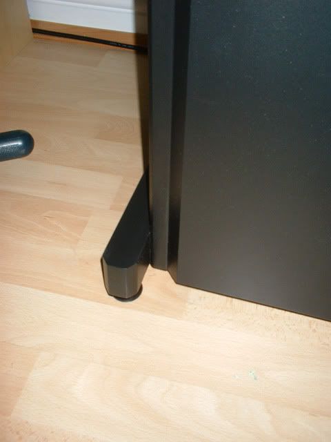
The front of the leg pieces have angled cuts to reflect the real machine.
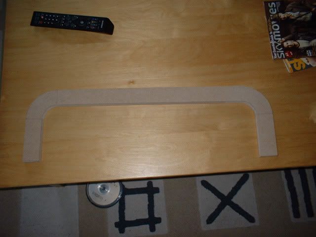
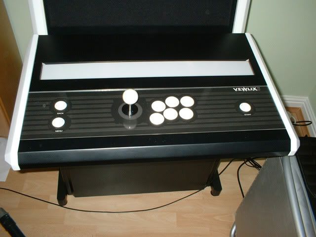
The following picture is to clarify the above:
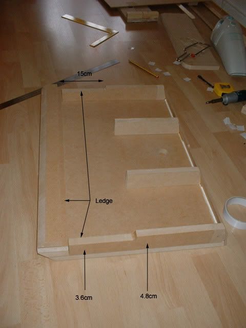
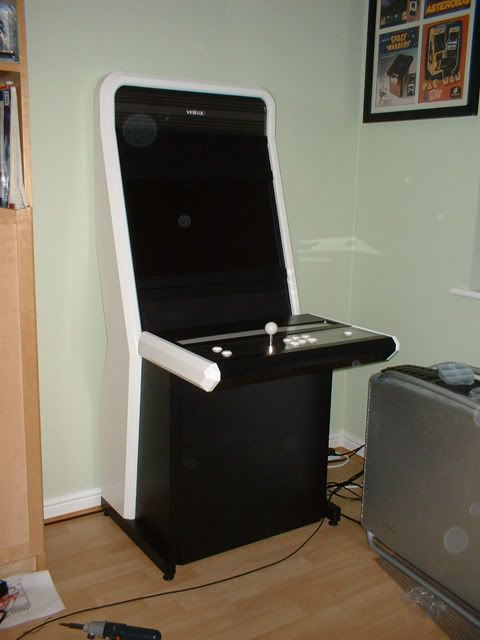
Front View:
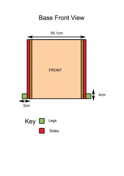
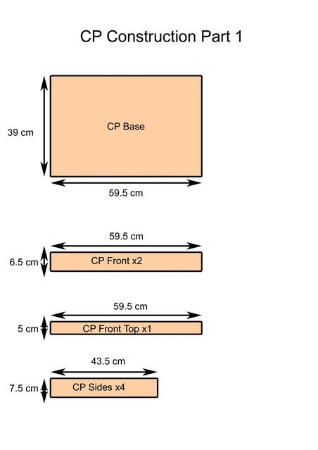
Plan description:
With the side pieces attached, the overall width is increased by 3.6cm. This is approximately 1cm wider than the monitor. It is important to base the width of the front, top and base sections on the width of the monitor, taking into account the thickness of the side pieces. My monitor is 58cm wide.
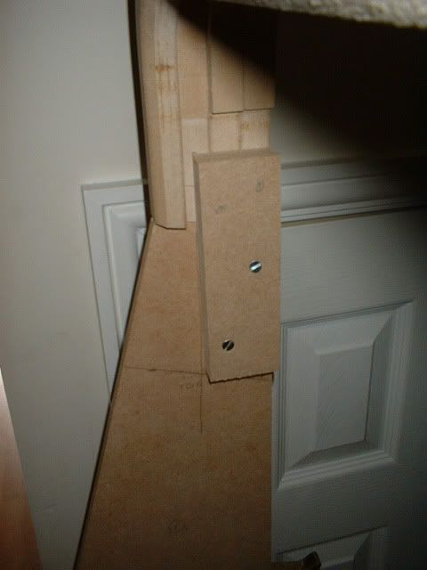
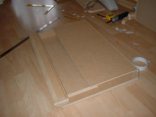
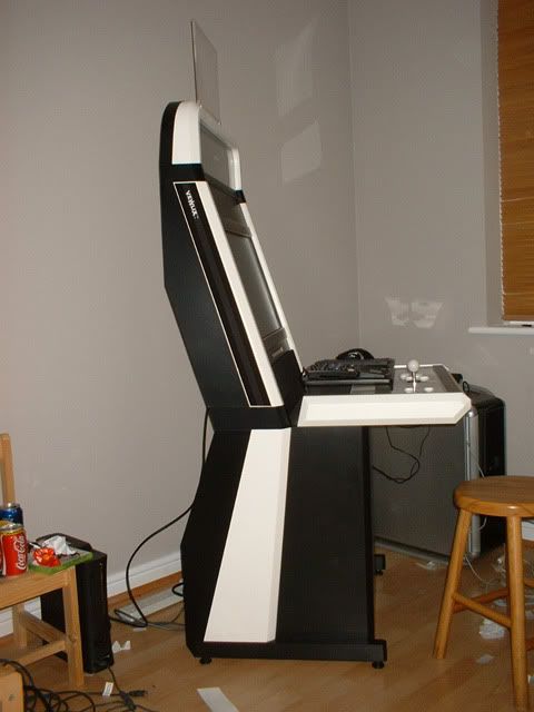
Construction:
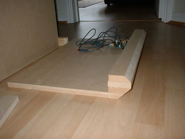
All the pieces were assembled and the pilot holes for the screws made before anything was glued together. All the main pieces are secured from the inside using the 25mmx25mm wood strip. This is visible in the following picture:
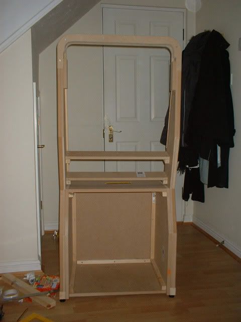
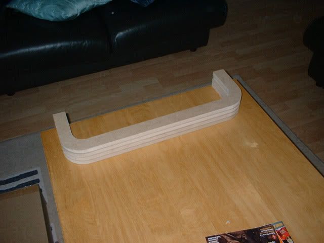
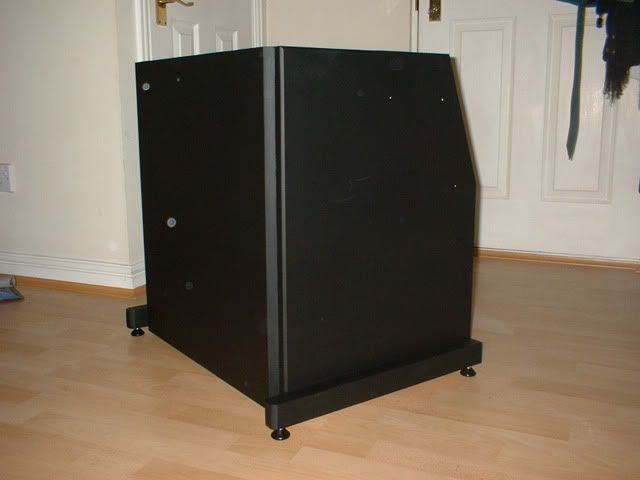
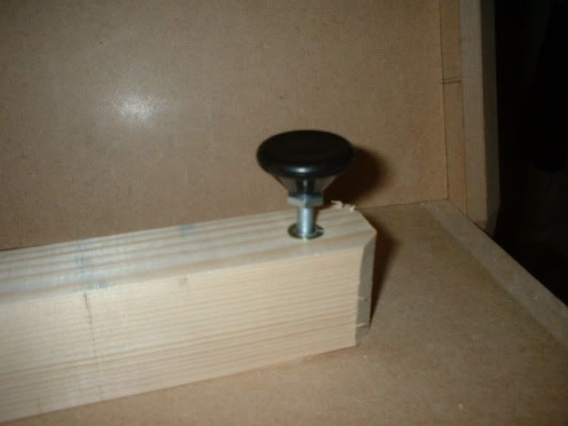
Once the dry fit was completed, The legs were prepared and the leveling feet inserts drilled. The following picture shows a test fit on some scrap.
The legs were then attached to the bottom of the side panels using the 40mm screws. 5 were used for each to provide a decent level of support.
Once the fit was confirmed, everything was disassembled and reassembled with screws and wood glue.
Notes:
You may chose to have your panels cut at your hardware store for pragmatic reasons but bear in mind that the cuts may not be exact.
A hole will need to be cut on the top panel to feed the cable through to the controls in the CP. You may want to wait to complete the base of the CP before you do this.