component cost will not shrink by very much at all moving to surface mount, the only opportunity for savings is on a small handful of resistors. However if board size is a bigger factor, i can probably compact the design quite a bit more, I left it slightly spaced out intentionally in order to ease modification.
I think there are diminishing returns when you shrink the board size so it’d probably be a better trade off to have the board be a bit bigger in order to be manageable rather than save a few cents per board. Is there any reason the board would still have to use the 18LF4550? It’s quite a huge piece and it’d be great if there were a smaller alternative.
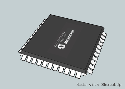
it would actually be quite difficult to change from the 1450, I don’t particularly want to port the code for instance and it has the right mix of peripherals for the job. However I used a TQFP package when i did the layout for this version. A 44 pin TQFP part is about half an inch a side and looks something like this:
http://4.bp.blogspot.com/_WRjFlgD5iW0/SXycDmnn1QI/AAAAAAAAALo/kYbH4CBgNFE/s400/pic16f887-qfp.png
its not very big, its just tremendously hard to solder with a conventional iron, which is probably why toodles went with the standard pdip. The biggest actual loss of space occurs because we need several headers on the board, if we moved to a different style of header we could save space but the ribbon cable method toodles used would have to go and it really is rather helpful.
My UPCB problems still exist; 2 of them go haywire whenever they’re connected to a ps2/3 after a few minutes of play [even holding down KKK doesn’t work for me anymore]. Also, the X360 piggybacks don’t work either [the X360 PCBs just blink once and aren’t recognized by the PC nor X360].
One of the UPCBs doesn’t work @ all [regardless of which PIC is inserted].
Would it be possible for me to ship my UPCBs to someone for them to look @? I would do it myself, but I have to ship my laptop to HP for repairs [button on keypad falling off], thus meaning I won’t have internet to look @ the thread.
I’ve been working on this project for over a month, and it feels like I’m back to square one since everything is breaking down on me for some apparent reason.
MAJOR EDIT: the images of the board pre Rev.A have been removed, here is a quick image of the current incarnation.
all other pertinent info can be found by scrolling down.
http://i171.photobucket.com/albums/u297/IKRENEGADE/UPCB-SMT-RevA.jpg
Ok I’m still having a problem with my output IDC to DB-15 wire. I’ve got a Rev 2.5 board and when I plugged it into my PC for the first time nothing happened.
Luckily though my UPCB has the optional DB-15 output coming directly from the board so I was able to connect it to my PC by connecting the Button Select cable onto that and everything worked fine and dandy.
Obviously this won’t be convenient for real use as I will have to open the stick every time i switch system cables so does anyone have a better diagram of how to connect the IDC16 to the DB15 output? Sorry Crime_in_Partner your diagram didn’t work for me.
Oh and I’ve tested the connections going between both connectors with my multimeter and they are definitely running the signal.
Here you go. hope this helps.
Like I mentioned, I based the diagram on my personal TE, so it should be right. Maybe you reversed the solder points on the DB-15? The colors are the order that the ribbon cable wires go into the solder cup end. Below are some screenshots from my TE. It’s not the best angle, but maybe it can help you out a bit with the directionality of the diagram.
Also, what’s this version 2.5 board? Toodles last board was a revision 2.1, and the firmware update on the chip was 2.5.
http://www.theitmaster.com/images/Tournament_Edition_Mod/TE_UPCB_2.jpg
http://www.theitmaster.com/images/Tournament_Edition_Mod/TE_UPCB_3.jpg
http://www.theitmaster.com/images/Tournament_Edition_Mod/TE_UPCB_5.jpg
You, sir, are a legend, a hero of our times! :tup: I had the IDC connector completely wrong. I changed it to what you had in the pictures and it worked great. Thank you!
Mine has a sticker saying “UPCB Rev 2.5BP” but yeah you’re right it’s exactly like the 2.1 board, must refer to the firmware.
Good to hear. Let me ask you, what would you have me change or add in the diagram to better clarify in the future, so if anyone else has issues, the diagram alone will fix them up without any further issues or confusion?
@IKRENEGADE
great great work!!! Please share your files…  Do you use Eagle. I’d like to have dc support, but it’s up to you of course. The idea behind SMD is of course to reduce size, but what do you think about adding 8 screw terminals for the buttons.
I can make a assembly service for the european guys out here. I’ve set up with Jason a batch with 30 DIL version UPCB and they’re sold out. When we now make the second batch I would say SMD is the way to go…
Great!! Awesome!! Good news!!
Changed the xbox360 PCB from saitek to madcatz. Now things are fine!
I’m just trying to make a couple of additional system cables, I currently only have the button select USB cable (which works fine I might add).
In particular the PS2 cable I’m having trouble with. I’ve tested and re-tested the pins, and I’mm 100% positive I’ve got the cable correct as per psx.h’s playstation button select cable (I’ve checked and rechecked several times!), but I can’t get anything out of the controller.
Is it possible that due to having a 360 pcb piggybacked that the 3.4V supplied by the PS isn’t enough to power both pcbs, and so it’s not working? Or is the UPCB clever enough to turn off the power to the 360 board if it’s not needed?
Any help greatly appreciated 
The UPCB doesn’t shut off the power to the piggybacked controller. If you’re worried about the piggyback controler(s) affecting things, it should be easy enough to disconnect them from the UPCB and test the cable without them.
I’ll put up some gerbers on monday, I used pcad to do the layout and schematic, if you want i can throw up the .pcb and .sch files as well. Regarding dreamcast support I did make an effort to keep it plausible without adding 2 headers and sacrificing board size if someone is seriously interested in doing it. I layed out the details in my last post, but i’ll repeat it just in case:
“EDIT: I forgot to mention that i also added cursory dreamcast support. Most of the pins on the DC PB header are located on other headers (the output header for the small 6 pin header, and Xbox PB for the larger 20 pin header). Noting this i ran the three missing pins out to some convenient test points to allow enterprising souls to either hijack the xbox pb header for DC or “padhack” the upcb to use both, classy.”
so DC is quite possible and actually fairly easy if the DC player doesn’t want x360 anyway.
As to screw terminals for ease of use, Basically right now the buttons are on a 20 pin header which is fairly easy to get to and can work off the same ribbon cable strategy as the db-15. As a result no actual soldering is required, however if you think screw terminals would have enough interest i can do a small daughter board with another header and a bunch of screw terminals. That would let people use a very easy to make cable to connect the two boards and put the terminals anywhere they would like, though it would be a bit costly to get a second board.
I’ll probably be ordering a small prototype batch of these for a few locals and myself soon, hopefully it works out, lol.
while double posting is generally in bad taste, here are the files for those interested parties.
http://www.mediafire.com/download.php?m22modmhqyh
edit: I just remembered to mention that I used the Guilty Gear button naming scheme for the pin labels, this might be confusing to some but it is quite simple to change, for now i’ll just say put up a quick translation
k = jab
s = strong
h = fierce
p = short
du = roundhouse
re = forward
Thanks. Have you prepared any documentation for assembly of the project? Any other changes in components or on the software side of it?
I set this board up to work the same way as toodles’ so every instructable other than assembly applies as long as you can figure out the new locations of the headers. I also labeled everything fairly clearly on the board so its unlikely that a separate diagram will be needed in this case. The only unlabeled header is the 6 pin ICSP that will be used to program the pic and its easily identifiable by the large triangle pointing at pin 1.
As far as assembly goes the instructable obviously won’t be much help, however the board really doesn’t have many parts and they are all clearly labeled so it will be easy to assemble with just a bill of materials handy, i’ll attach one with the digikey part numbers listed.
The software will not need to be modified as there were no hardware changes that the pic can notice.
I also revised the layout to add the fuse, don’t know how i left that out, coulda been tragic. I changed the labels to street fighter notation as well. However i left the schematic in GGXX notation because i don’t expect that anyone other than me needs to use this particular schematic as it is electrically equivalent to toodles’.
There is now a readme in the zip, it should explain most stuff, if there is something you want added to it just let me know.
new files:
http://www.mediafire.com/download.php?ozizermkzzi
I also put in the pcb and sch files for the screw terminal daughter board.
hey, thanks man
Alright, here are the final files for Rev.A of the smt upcb. I made several changes in this version and fixed a small bug in the schematic, i have ordered a prototype batch of this revision and will have data on it in a week or two. This zip does not include gerbers for the daughter board and is specifically for others to fabricate this project.
http://www.mediafire.com/?jtyyz2zmtv3
If there is interest I can do gerbers and documentation for the daughter board. I’m also open to suggestions to further improve this project in future revisions.