Im just trying to update the firmware from the bootloader, but i get a device not recognized
error. I found my soldering for the idc to db15 cable had come apart, I completely redid it
but still no go. I trying this on a laptop with xp if it makes a difference.
Obvious guess would be, if everything worked before the soldering had come apart and now, after the re-soldering job, it still doesn’t work, that there is a problem related to your re-soldering of the cable. You don’t happen to have any pics do you?
upgrade firmware
actually it never worked, i was only able to program the chip through iscp.
dont have pics will try to take some.
Check the voltages on the XBOX_PB_SELECT and DC_PB_SELECT lines when its plugged in; both should be low. Then, check the voltage on both sides of the PTC fuse. If too much current is going and tripping the PTC, the the power to the boards will be cut off.
First off, make sure the only thing you program the chip with the iscp is the BOOTLOADER.HEX. Do NOT flash the regular UPCB hex’s using ICSP, otherwise you won’t have a bootloader available. The BOOTLOADER.HEX uses an older version of the UPCB code along with the bootloader itself, so if the cable is properly wired, it should come up just fine in either joystick mode or bootloader mode with just the BOOTLOADER.HEX code.
But wiring up the outgoing IDC->Dsup part can be confusing. You’re going to have to spend some time checking both the D-sub and the console cable you’ve made. The easy way to check the d-sub is to check for continuity between the dsub pin on your IDC->Dsub piece, to the matching point on the board where the d-sub can be directly soldered to the board.
gave up on the idc to dsub cable and just soldered dsub connector to pcb directly. UPCB is now recognized as pic device. I think i upgraded the firmware, how do i get it recognized as a controller?
do i need another usb cable wired differently?
thanks in advance!
ps. i did use the bootloader.hex initially with icsp
Use usb button select cable, which is default ps3/pc and gives you bootloader when start+select are pressed.
I thought i had made the button select usb cable, but upon
rereading the allusb.h it looks like I made the bootloader cable.
my mistake, thanks.
Easy to mistake since the only difference from the button select
cable is pin 15 is tied high on one and low on the other.
I’ve chopped up my TE stick to be dual modded with the upcb, but I’ve run into a problem. The upcb is working fine when I use it in PS3/xbox1 mode and disconnect the cable connecting it to the TE pcb. However, when the 360 pcb is connected (even in ps3/xbox mode), I get about one input then then joystick stops responding until I disconnect the 360 pcb. I suspect it is because I am using a 4066BCN instead of a 4066N to handle the switching, but my local store didn’t carry the 4066N.
Can anyone tell me if there is any alternative to the 4066N that will work? I don’t know how to read the datasheets.
4066N Datasheet: http://pdf1.alldatasheet.com/datasheet-pdf/view/15618/PHILIPS/74HC4066N.html
4066BCN Datasheet: http://pdf1.alldatasheet.com/datasheet-pdf/view/173187/FAIRCHILD/CD4066BCN.html
I dont see anything that would suggest the BCN wouldn’t work. If you want to be sure, pop the chip out but leave the 360 pad connected; it won’t hurt anything but you wont be able to turn on the 360 piggyback. If the same behavior remains, then the first place I’d look is at the PTC to see if its tripping from too much current.
Ok tested, and it behaves the same. The fuse I am using is 0.3A. Can I test it by plugging the board in and measuring the amperage with a multimeter at the fuse? Or is there a better way to do it? If I have to swap out the fuse, what is the highest amp rating fuse I can safely use without risking the board?
You could test the resistance of the PTC after its plugged in and borked, or just test the voltage at the VCC test point.
If its already blowing a 0.3A fuse, then you’re already in the grey zone. Only guaranteed power amount from USB is 0.1A. You’d probably have better luck either removing all extraneous power using stuff you have (in case of a p360 or flash, LED mods, etc.) and removing the guide LEDs from the 360 pad and checking the resistors used in any trigger hacks to make sure you’re not wasting power by them.
The UPCB is GREAT, but I’ve ran into a few snags after the project’s competion:
1.) I got the UPCB w/ X360 piggybank to work for a few days. Yesterday, while playing SF4, it constantly disconnected [whenever I inputed Sim’s KKK instant teleport command]. Reseating the PIC card usually fixes the problem, but after reseating it a few times, the issue still came about, then finally, the X360 wouldn’t recognize it as a controller.
So I got another X360 Madcatz PCB, and resoldered everything as the instructable guide informed me of doing [i.e. the EXACT same way as before], and the PCB still can’t be recognized. I even put the X360 PCB into my other UPCBs w/ the same result.
2.) After realizing that my PIC card kept falling out, I decided to add a bit of force to push the pins in, and it’s seated perfectly now [only the smaller portion of the pins are secured into the holder]. I connected my UPCB to my laptop to test the buttons and they all work fine. Then I connect it to my PS2 and all of the buttons work fine…except jab [square], which is weird.
Help is much appreciated, and Toodles, how far along are you into your new UPCB?
**Update: **
1.) Crime_in_Partner told me about button remapping for the PS1/2 by holding KKK during plug-in, and jab is working again.
2.) The resistance on the X360 PCBs are about 3 ohms. Is there any way to change it to infinite? Even on an empty X360 PCB, it outputs about that same amount of resistance.
Hi Toodles, first of all I would like to say great work! I was stoked when I found out about the UPCB’s existance! Secondly, sorry to be asking another noobish question!
I know this has been covered in the last few pages but i too am having problems with the cable from the UPCB to the output DB15. I don’t know if pin 1 refers to when you look at the business end or the crimping end.
I mocked up a simple drawing of what I have just now:
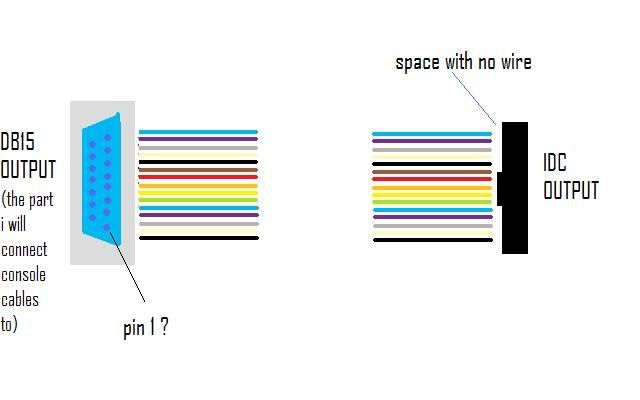
The black wire at the bottom is the ground so I think it is all ok at the IDC end, i’m just not sure about the DB15 end (The DB15 is facing the right way so it’s as if you’re looking at the back of the stick). Do I need to flip it around or is this correct?
Thanks
The only pin numbers talked about there are dsub pin numbers, the ones written on the dsub connector itself. You say the black wire in your picture is ground, but based on where the notch is on your picture, I’d have to disagree. Read over these directions and let me know if anything is unclear.
My understanding from your previous post is that for the IDC connector if the black wire is Ground (the bottom-most point) then the missing wire is at the furthest point away (the top).
Did I have pin 1 for the D-Sub in the correct place?
Here’s a diagram I made to help with how the ends of the ribbon cable need to look like on the DSub and IDC connector ends. The ribbon cable colors are what you would get if you had ordered the one from Digikey that Toodles has in his UPCB Instructible. I based the diagram off of how I have my UPCB wired in my TE. You’ll notice that the 16 pin IDC connector is staggered like the D-Sub connection. This is because the connector has staggered teeth that need to match the diagram. Also, the dashed circle on the IDC connector for pin 16 isn’t used.
http://www.theitmaster.com/images/UPCB_Diagrams/DB15_to_IDC_connector.jpg
Now that is pretty.
Lol.
Thanks Crime_in_Partner, that diagram makes it a lot clearer!:wgrin: And you beat mine for prettiness. :sad:
I would definitely find it useful. I originally looked into getting fully/partially assembled boards made in china, but one of my worries was component/labour cost. If the pcb surface area could be shrunk and the assembly process done more efficiently, it may become cost effective to do.
I sense I am getting very close to fixing the problem. Of course I discovered that because I didn’t properly RTFM, I assumed the order of the pins in the ribbon cable were sequential. I’ve redone all the connects from the 360 output on the UPCB, and now the stick is almost working properly while connected to the 360TE PCB but in PS3 mode.
The only problem now is that in PS3 mode with the 360TE PCB connected, the stick is constantly registering left on the joystick. All the other directions and buttons are working fine in PS3 mode with the 360TE PCB connected. Behaviour is the same in xbox1 mode.
All inputs work fine with the 360TE PCB disconnected.
I am not quite sure how to test whether the fuse is being blown or not. When I test the resistance at the fuse, for some reason I get different values depending on the scale setting I am using.
The 360TE PCB is not being detected by the 360 when I boot the UPCB into 360 mode.
I have checked the voltage at the USB input on the 360TE PCB and the 360TE PCB is only getting 2.9v.
There are no triggers and I have tested with disconnecting the guide button leds and turbo buttons as well with no luck. What else can I do to find the problem?