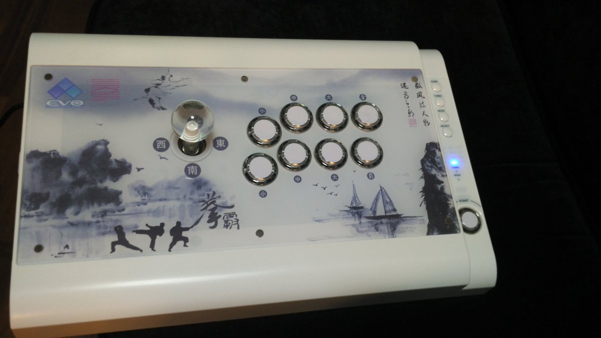
Dremel the heck out of the plastic shell.
So I did what you advised and just only connect the button inputs from my secondary PCB to my main PCB, but the LEDs are not working?? DO I need to someone get extra ground and VCC from somewhere to get the LEDs to work?
See this simple picture I drew up below, hope it make sense.
Which stick/LED controller do you have again? you should only have to wire your signals together and call it a day. Your diagram looks correct, aside from there being 2 grounds on your LEDs. Usually, the LEDs ground is connected to signal, so when you press the button, the LED activates.
@Vicko I have the White Qanba Ps3/ PC EVO blue LED arcade stick.
On the main board, there are the usual ground and signal wires, then two other wires which is for the LED. So in total 4 wires per button.


yeah, this one’s weird. You have to solder to the other one that says the button label, so not the one next to GND, solder to the one next to vdd. Try that, just with one button to start.
okay, I’ll give that a try 
@Vicko
Okay, I tried connecting to the other signal as you suggested, but neither the button or LED work at all.
For testing sake, I then tried linking the two signals from the main board and it works, BUT it I was to switch from PS4 mode back to the original platform (main PCB) this causes issues as the is a constant connection for both due to link I did…
Any other suggestion? It seems both the LED and button requires a signal, the VCC is there as both boards are always powered.
Solder ps4 button signal wire to the button signal that is left to the gnd. Cut the wire that is right off vdd and solder it to the that same wire left of gnd.
@Gummo @Vicko
Hey guys, thanks for helping out, so if I understand this correctly.
The PS4 signal goes to the left of GRD as normal, then cut the signal right of VDD and connect that to the signal left of GRD (with the PS4) as well?
If this is the case, what will happen if I switch the platform back to PS3? would the original function still work? eg LED and buttons?
Yes, since both the signal and led will be grounded when you press the button, both will work as normal regardless of mode
The leds and buttons will still work on ps3, but you will lose the led “effects” the qanba can do with the leds. They will only be light up on press for for all systems.
@Gummo @Vicko I got the buttons to work witht he LED in PS4 mode thanks for the help.
How would get the joystick to work? There is the normal 5 wire that goes from the PCB to the stick, then there are two more wires from the PCB to the stick as well, this is for the LED.
The LED would light up when a Direction is triggered. I thought of using the same for what I did for the buttons, but couldn’t figure how it works for all four directions?
Cheers.
You need diodes on all 4 directions
for the third pictures that shows the bottom of the pcb where r1 and r2 are, r1 is 1, r2 is 2. is the number three still the ground like the older fc4? I really wanna know because that’s what I used to wire all my grounds to my last pad hack and it was pretty easy. thanks.
Yes. If you’re not sure just beep it out with a meter.
awesome, thanks.
Mad Catz Street Fighter V FightPad Pro
http://i1015.photobucket.com/albums/af274/misterjessejames/Pad%20Hacks%20and%20Measurements/fightpad%20pro%20cover.jpg
Chun Li clothes… err, I mean controller shell  . I don’t have a picture of the controller intact, so this will have to do.
http://i1015.photobucket.com/albums/af274/misterjessejames/Pad%20Hacks%20and%20Measurements/fightpad%20pro%20front%20labeled.jpg
PCB top side with labels.
http://i1015.photobucket.com/albums/af274/misterjessejames/Pad%20Hacks%20and%20Measurements/fightpad%20pro%20back%20labeled.jpg
PCB bottom side with the utility switch removed and labeled.
Good news is that the controller is common ground. Bad news is that the triggers need inverting.
Extra Read
Ran out of thru hole hex inverters so I bought some surface mounted hex inverter in bulks on eBay at a reasonable price and when I received it, did not expected it to be really small.
http://i1015.photobucket.com/albums/af274/misterjessejames/Pad%20Hacks%20and%20Measurements/hex%20inverter%20size%20comparison.jpg
Smaller than a micro SD card.
Got 30 awg wire, magnify lens, and patience… it is at least manageable.
http://i1015.photobucket.com/albums/af274/misterjessejames/Pad%20Hacks%20and%20Measurements/hex%20inverter%20wired.jpg
At least it is not as difficult as soldering wires onto a 0402 SMD LED.
After wiring, needed hot glue so that it will prevent stressing out the solder joint.
http://i1015.photobucket.com/albums/af274/misterjessejames/Pad%20Hacks%20and%20Measurements/fightpad%20pro%20front%20wired.jpg
PCB all prepped up.
After seeing all those bad reviews on Amazon of the Mad Catz controller, at least the PCB is good. 
If I am only going to use it for a 6 button ps4 stick and won’t be dual modding, is it possible to ignore the triggers completely and not invert them?
Sure. It just means your button mapping won’t be like the standard.
Also note that even though it is common ground if used in a dual mod it’s inputs will be held low when the controller isn’t connected to a ps4/ps3. It will need diodes for all its inputs. In your case you won’t need to worry about that since you are making a ps4 only stick.