For clarification, the offending part that needs to be wired https://drive.google.com/file/d/1d0kfsHaSyRXmGh6oK-ZeLBEaWfJ3L5YN/view?usp=sharing
and
https://drive.google.com/file/d/1POYcOFutqPL7CENa88MIyhG41FG2laiY/view?usp=sharing
Yeah I know. But why can’t there be third party cables?
A few people make DIY cables for the Panthera ans TE2, myself included. But if you had to choose, would you pick the OEM cable or a cable some guy on the internet made in his garage?
I have made 35 usb cables for TE2/TE2+ and none of them have failed so far.
So I would say it depends on the guy who made these in his garage lol.
I just picked up an XB1 Atrox along with the Brook UFB. My first time doing modding like this and everything seems fairly straight forward except for the lock/home/player LED. How do I connect these to the UFB? There are 4 wires coming from that secondary PCB (1white/3black), all attached to a pin connector at the other end. How do I connect these to the UFB?
How did you connect the home/player LED/lock buttons to the UFB? The wire which looks like is coming from the home/lock board in your pic looks diff than the stock one I’ve got. Do I need to replace this?
@HypeBe4st Just got myself a that brook ps3/ps4 board with audio and everything was easy up to the Home/Lock/Led part.
Did you solve your issues? If so, what did you do?
I’m sure this has been asked before, but how’s the Panthera performance? Any noticeable issues? How’s the build quality? There’s one on sale at my local GameStop and I’m considering picking one up.
Its really good. More sturdy than the te2. Not sure about the lag since it really doesnt matter. Mine has no issues so far and is my daily stick. Do you mind me asking how much it is at your gamestop?
On PC it doesn’t recognize R2 and L2 as buttons so you can’t use them unless you rewire the buttons. PC will recognize them as z axis. Either way you are still left with 6 instead of 8 face buttons.
I’m still looking for a solution.
The Brook board I’m using is the UFB so there might be some differences between mine and your PS version.
Here’s a pic of the UFB along with the lock/home board with the wire that connects to it: https://imgur.com/TERP9Bd
I’m just unsure where these wires go on the Brook UFB.
jasens customs has a cable but it will require a little rewiring but if you have a brooks it will work perfectly
I have my kaimana mini powered, but I cant get it to connect to my computer. Shouldnt I be able to see it with all the other drives? I have arduino started but I cant edit the code because I dont see the file on the cpu. Any suggestions?
After a few hours of reading the threads and searching this forum, google, and youtube I haven’t gotten any further and I am hoping someone can answer some basic questions for me.
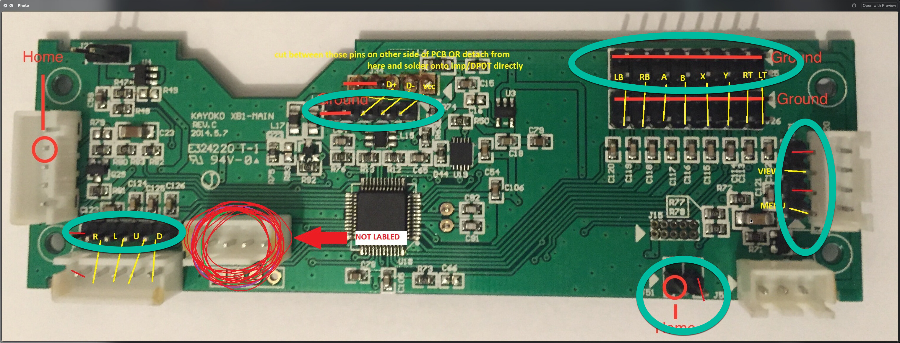
I have the Razer Atrox for XB1 and want to mod it to use the Brook UFB.
- Can I keep the original Razer Atrox PCB in Place and use jumper cables to connect the Brook UFB? This seems logical since the Razer Atrox XB1 PCB has header outputs for all the things we need. Is my understanding wrong?
See image, couldn’t i just use jumper cables on the green highlighted headers and connect them to the Brook UFB?
Go back and read up on Dual modding. There a thread that should explain everything.
Be warned, the images could be broken as it’s a old thread and it’s creator no longer comes to the forums.
I would also take a minuet to read slagcoin.com . We consider it required reading here in Tech Talk.
It is a dated site now, but it covers all the basics which hasn’t changed. Only part that is out of date is the PCB section as it only covers up to early PS3 era boards and nothing further. The tips on wiring haven’t changed ether.
But I will show you the main points of doing a Dual mod.
The Two Golden Rules
- All boards need to be powered
- All boards needed to be connected to Ground
For Power in this case, both boards VCC needs to be wired to each other as in having a wire from one VCC point to the other VCC point.
And you do the same thing to Ground.
You can chain the inputs together, just know that only one board can have it’s USB connection at one time.
That is helpful thank you.
Reading up on the available dual mode info, I don’t think its reasonable to keep the original Atrox XB1 PCB anymore since keeping it is more work than it is worth. The Brook UFB supports all major consoles so its better to just use that as a single board.
My next question is with the USB connection.
The connection coming from the Atrox XB1 USB port is 5 wires.
The Brook UFB takes in 4 wires for its USB connection.
Do I just hook the two grounds from the Atrox XB1 USB wires into the 1 ground of the Brook UFB?
See Diagram.
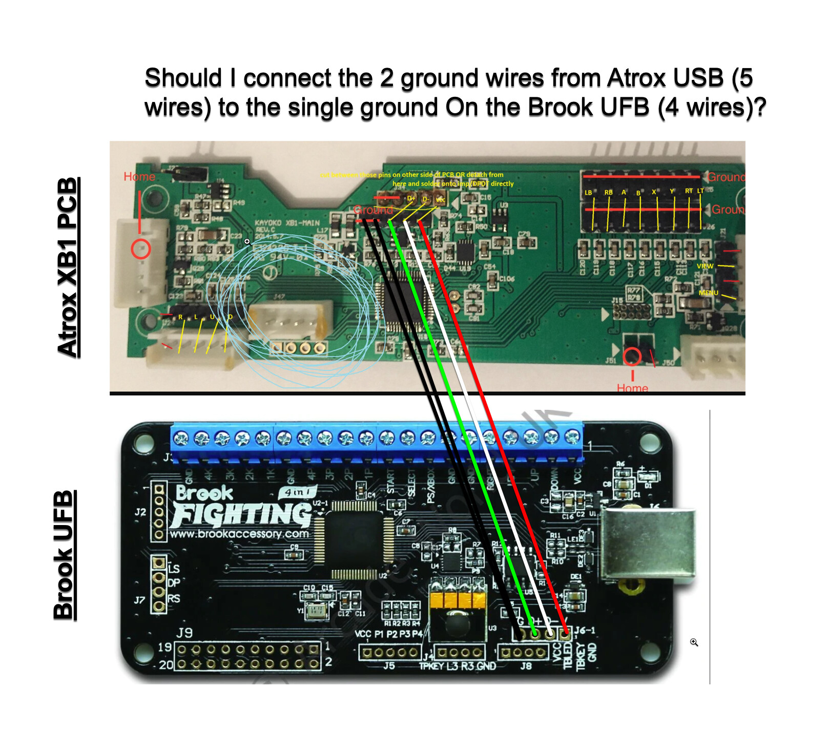
There an extra ground called thw shield ground, it’s justbthe shielding in the cable being tied to ground to isolate interference.
I usually tie those wires together
With most of these controllers and other cost conscious devices, the shield wire is tied directly to ground. However, the recommended design is for the shield to connect to ground through a inductor/resistor with a capacitor installed in parallel to the resistor to reduce RF emissions and potential interference with other devices. Better than 90% of the fight sticks I have seen have the shield connected directly to ground but never hurts to inspect the pcb and test each potential ground wire for resistance to ground with a meter when necessary.
@Darksakul has is right though, if you have a ground and a shield line, you can tie the two together directly to ground. Nothing bad will happen but if your AM radio is blasted with noise, you know why. 
1 Like