*The "padhacking" thread*

Sorry, i should clarify.

I did listen to you and your advice was very helpful, but my original question was in reference to modding a Hori EX stick. I wasnt sure if i wanted to mod a pre-made stick(the hori) because it would be easier, or if i should try to hack an xbox PCB and do the whole thing from scratch(way harder from my point of view)
But i tried the 360 PCB hack and amazingly enough it works and tests great. So i scrapped the idea of modding the hori and went ahead and built the box from scratch and wired it all up. Everything is done and works except the dpad.

So now my NEW question is about that common ground issue. I thought i had a workaround because i found the soldering terminals on the top side of the JLF pcb and figured those grounds would suffice. Turns out they didnt.

So: is there a way to connect the dpad on the xbox pcb to the common ground JLF pcb?

thank you~
Look at the Joystick Connection subsection most the way down this page; I think I have covered the options there:
http://www.slagcoin.com/joystick/pcb_wiring.html

Hey thanks Slagcoin!

I didnt know that the wired 360 PCB has 3 different grounds. So i severed the joystick pcb and now they have independent grounds. That just fixed 99% of the problem.

The last part of my problem is this: every connection works now except for “left” on the 360 dpad. Whenever i complete the circuit on that button the 360 PCB shorts out and turns off until i break the circuit and then it comes back by default.

What could cause that?is there a chance my soldering of that point is accidentally making a connection with another line in the circuit?

thanks~
alan

Sounds like you stuffed something up with the wiring. The left button should be no different to any other direction.

Yeah, one way you can fix the problem you had was to cut the traces on the JLF board and solder each micro switch connection to be independent which is what you’ve done by the sounds of it (or you removed it totally). A better way would have been to solder the black wire to the common signal connection instead and the other wires to the ground connection of each direction. It works as it still creates a short.

thanks man, anyone know if i can get a stable sv connection from the psx pad?

Maybe I’m reading things wrong, but would that not work because up and down share the same ground?

When I take the ribbon of the sixaxis off and add resistors http://www.slagcoin.com/joystick/pcb_diagrams/ps3_diagram2.jpg

does this mean add to both 7 and 8 pin or bridge these together with the resistor? I’m sorry I’m not very good at reading the diagram also do I just solder a resistor to pin 14?

So i bit the bullet and abandoned that pcb that had a short in it and started a new one for the third time. Sure enough, third time’s a charm and it works great! What a relief, that stuff is hard.

Not to look a gift horse in the mouth though, i did notice something strange. It works perfect for street fighter HD remix and perfect in all of the xbox menu navigation, etc, but for some reason soul calibur from xbla doesn’t work with it. The game thinks all kinds of buttons are being continuously held that aren’t, making it impossible to play.

Anyone ever seen a custom with “discriminating” functionality?

The PCB looks for a restricted communication between pins 13 and 14, and 7 and 8. So there has to be a path with a restrictor bridging those. I have a couple solderless PS3 images a few pages back in this thread that might make you understand it. You might want to look at your face ribbon and the paths with resistors to understand it also.

I have no idea about this.

SC1 is fucked up. I couldn’t get it to change buttons in the options for the life of me, and it acted completely weird with my stick (piggybacked pcb from a DOA4 stick) so I don’t think its just you.

Yes, and it’s mentioned in this thread a couple of times by me. I have a little board, about 1"x3"; you connect five or six wires on one end (one for each direction, one ground, and if you need it for a flash or p360, +5v), and ten connections on the other end (two wires for each direction, +5v power, and ground). viola, Common ground stick can operate non-common d-pads.

The xbox 360 has" street fighter 2 turbo HD remix" already? I thought they were still working on this game. How can I get it for my ps3 or PC?

yes, I was wondering about other ppl experiencing weirdness in other games like VF5.

Toodles has a little board you can buy. Otherwise you’ll have to dremel/damage the pcb so that the ground is cut and each microswitch is not grounded together. You can dremel between where the microswitch meets the pcb on the jlf and still be able to solder back with wires if you need to.

It’s just the beta. The final version “should” come out 8 weeks after the beta. I don’t know if a PC release has been confirmed yet.

is it available for ps3? Or will it ever?

i think they mentioned on the capcom blog that there wont be a beta for ps3. something about LIVE being easier to program with than the playstation network so they were able to take less time prepping the beta. it ends in august as far as i know.

Questions, thanks and such

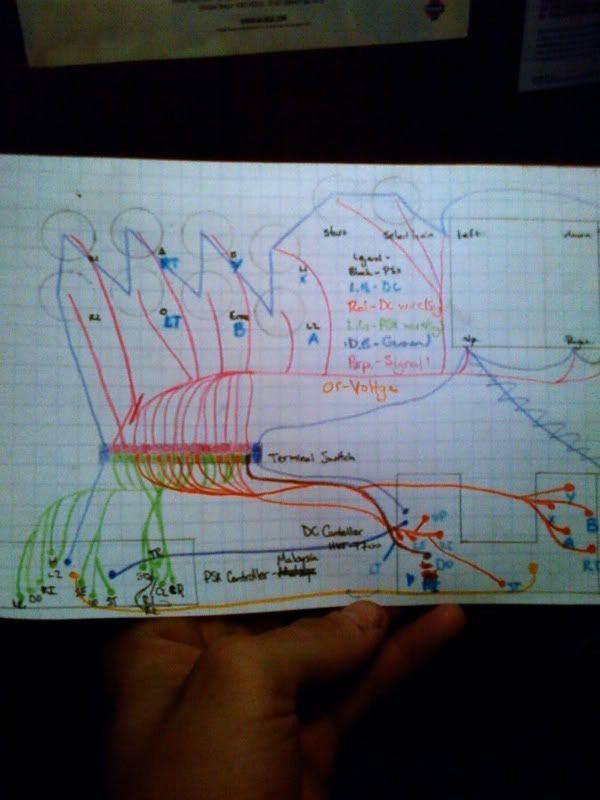
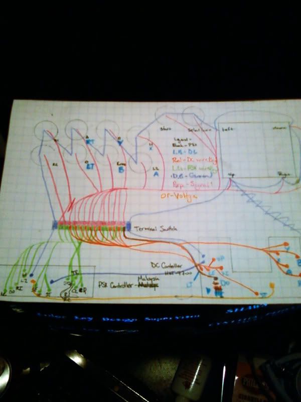
I just had a couple of questions. I’m building a stick with a dual PBC (DC/PSX Compatibility) and I’ve finished drawing-out my circuit. Now, before I begin building, I want to make sure that my schematic is right. Well, if you can follow it, is it? If higher quality is needed, I can scan it.

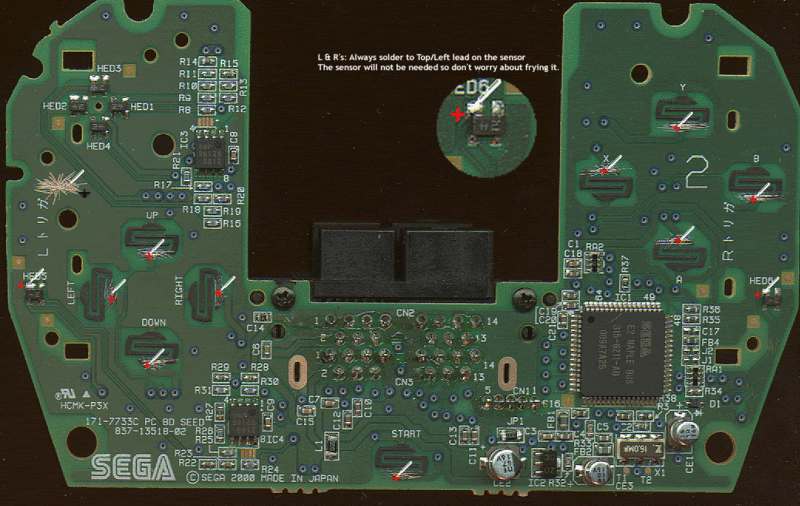
This is it. As you might see, the ground circuit connects with all signal-wires. I’m not entirely sure where the ground is in the DC controller, but I have a good idea. According to a source (Paik, I believe), the ground can be scratched close to the crescent-etch above the one supplied by the picture below.

I see one area where a ground can be formed (the scratch located next to the cross, in the area above the D-Pad) however I don’t know where the second ground goes. Can I place the both ground wires in the same area?

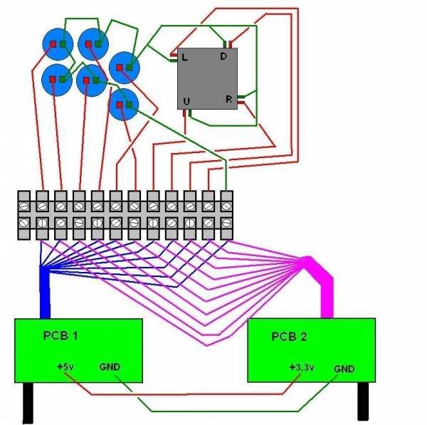
Here is the diagram I used to guide me through the process. As you can see, the 5+ volt and 3.3+ volt connect. Is this necessary? What would be the end result if I didn’t connect them? I assume that connecting them will cause both PBC’s to power up when one pad is connected to the console.

I also have to scratch off the black coating covering the copper, right?

Any help is greatly appreciated.

I’d also like to thank those who have made all of this possible with the information they’ve provided. The Real NeoGeo, Shoo, Toodles, ChipperMonkey, Timoe (or the external work), Paik, Slagcoin, Tetsuosan and anyone I forgot to mention on SRK, you have my gratitude. Thanks guys.

Quick question, is there any reason why you’re doing a dual pcb setup with a dreamcast? The only reason I ask is that the EMS dreamcast converter is lag free.

To answer your question as to why you need to solder both the power and ground lines together on the pcb, is that if you don’t the controls will start going haywire.

Yes you also need to scratch off the black coating for the copper.

It’s cheaper to rip the guts out of something I already own and rarely use than it is to get a converter. About $18.99 cheaper.

Thanks. As soon as I can find another ground in the DC controller, I’m good to go.

The pic you posted was of a first party, Sega made, DC controller. DO NOT USE THOSE!