Just hit up ebay, there’s a ton of listings with digipads, all of which are hackable.
so on the PS1-H, you can solder to the little points on the PCB, and you dont have to scrap off the black shit, Then you can cut off the sides and fit it better into a project box.
But there are a few points that look a little confuseing and i dont want to fuck with um. Can you solder the buttons to the little points and then scrap the black stuff off for the D-Pad or does it matter?
I have a pic if my wording is a little confuseing…
I noticed that too. I need to sometimes thread an insulated wire through small holes. Did you manually check the wire in a shop or something? I need thin wire, everything is fat insulated!
Nah, I got it online, so I had not too much of an idea of how thick it was. I bought some Radio Shack 24 AWG wire at first, which was pretty disappointing; they must think it has to be compatible with cheap stripping tools or something.
I got it from a store named Electronics Plus, part number 24/25PT. It was gutted from some thicker 50 24 AWG outdoor wire costing $1.30 a foot, which isn’t bad for 50 feet of wire. Shipping will cost you though (I ordered a lot of stuff together). I dunno, I might have to have at look at some local stores to see if they sell this kind of wire.
http://www.electronicplus.com/search-return.asp?search=24+gauge
Preview of an image I’ll add in my website’s next update:

Do happen to have any pics of your progress?
:lovin:
Can I put a PS PCB on a Saturn Model 2 Controller…is it even possible
has anyone had issues with wiring up the pcb to Sanwa stick micro-switch (TA-MA)?
I use common ground and used JLF cable but all directions go right only.
When doing individual ground option it will work goin left and right but up & down directions while not work?
is their any particular reason for this?
help would be much appreciated
I have a problem with a orig. MS 360 wired Pad that has been installed in a DC stick. All of my games work despite of Virtua Fighter 5. Buttons are not recognized and directions won’t work properly. Any suggestions?
slagcoin thx for the info, I found a 15-core wire with thin insulation, i’ll have to use that from now on cos everywhere else is fat insulation.
Patmaster I think I saw that problem b4 and couldn’t remember if there was a solution. Don’t think there was.
Hmmm, I wonder if you found it at a local store of yours, because I’m wondering if its practical to recommend certain local stores for finding this stuff.
Anyone know of a link to a good Wireless PS2 Padhack?
Am i correct in thinking the only difference would be that you need to solder a little batterie holder to where the only one was on the PCB and then just do a normal padhack??
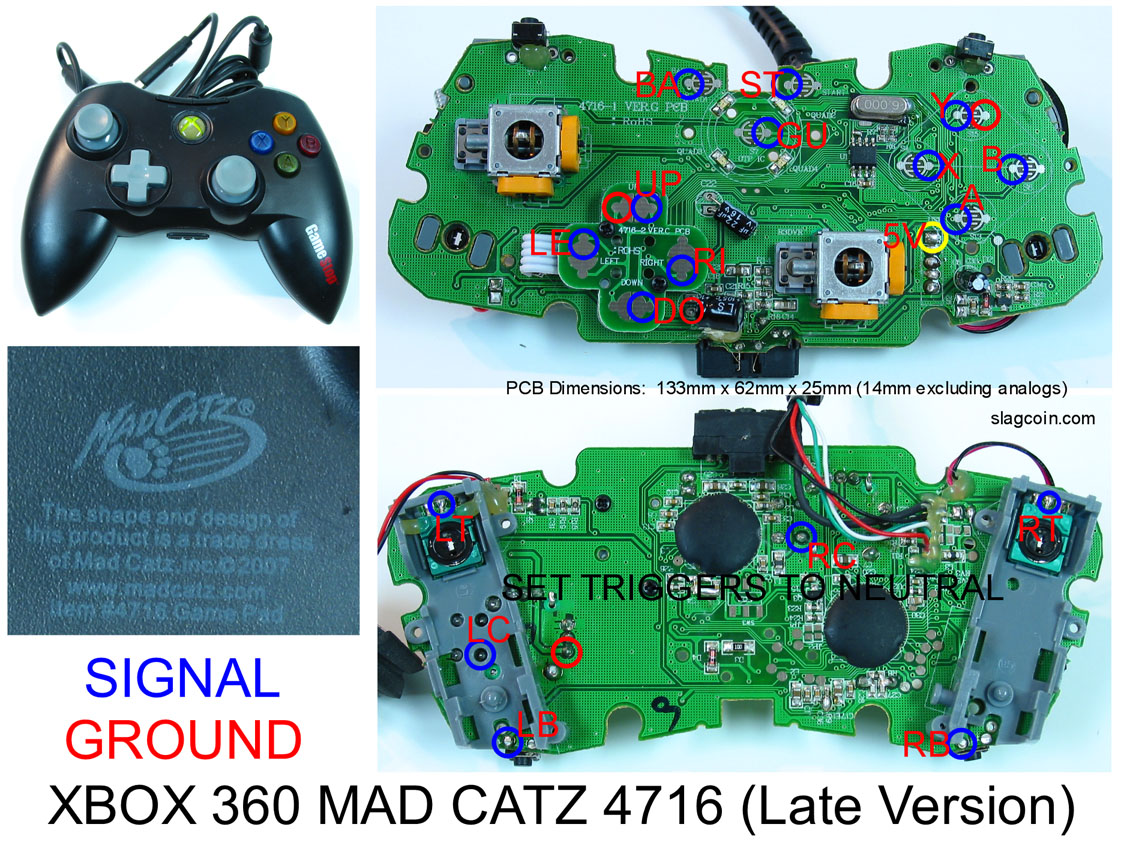
Can somebody tell me where do I solder ground to on the Mad Catz Xbox 360 controller? When I plug in the controller with everything wired up it keeps reading the direcitons as the xboxLive button. This is the pad http://www.ebgames.com/Catalog/ProductDetails.aspx?product_id=42850
Posting a link to the controller won’t help. You need to post a good pic of the PCB itself. Not enough information to know anything for sure, but the first place I’d look is to triple check it is actually a common ground controller and not a matrixed one, and then to doublecheck your wiring.
I was at work and really couldnt access my home computer at the moment. Anyways I was trying to the wiring like this: http://www.slagcoin.com/joystick/pcb_diagrams/360_diagram3.jpg But can some one explain to me setting the triggers to neutral? Another thing, so in total I need 3 ground wires? One for directional, one for X,Y,A,B,ST,BA,GU and one for triggers and bumpers.
Along the way I found this: http://forums.shoryuken.com/showpost.php?p=4762858&postcount=931
Which essentially means I need one ground?
Any help is much appreciated, thanks.
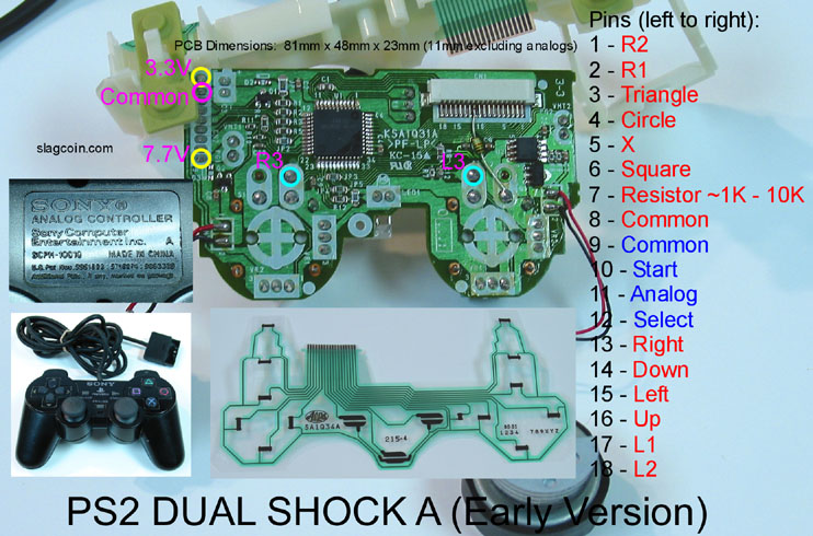
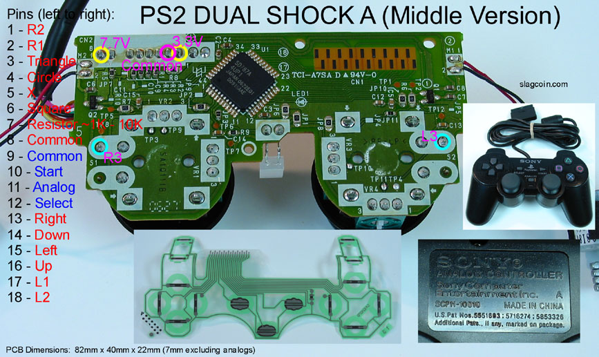
Can anyone point me to a tutorial that uses soldering for an A series PS2 dual shock? Funny, after seeing pick I dont have that white housing holding the ribbon, it just sits there.
My PCB is a combination of these 2 boards:
http://www.slagcoin.com/joystick/pcb_diagrams/ps2_diagram1.jpg soldering point run down the left. However, the ribbon connector (or lack of) looks like this one:
Hi all,
Finally modded my stick… Madcatz arcade pcb for 360. Connected the LT and RT triggers as shown in the LT + RT thread. When pressing either trigger, the pcb fires LT, RT, left and down. When pressing either LB or RB, both LB and RB fire. Everything else works fine. What gives?
Edit: I also noticed my Mode button doesn’t work consistently, and I know it’s not the wiring… usually only works when I’m plugging in the controller. WTH?
First arcade stick; help please
I bought a Gamestop brand psx/ps2 compatible controller (I think the wrapping said it was a micro controller). Here’s the inside:
http://i10.photobucket.com/albums/a142/harurenge/P1010021.jpg
Can I get help on figuring out where the signals and ground are for this PCB? Thanks kindly.
i hAVE THE PS2 DUALSHOCK a SERIES WIT HTHE RIBON. COUPLE questions. do i need to keep the ribon hooked up? and on the slagcoin diagram it says resistor on pin 7. i know what a resistor is but where does the other side go? 1 end of the resistor on pin 7 the other side? also there apears to be 2 grounds. 1 for start select and analog and 1 for everything else. is this correct?
this is the pcb i have http://www.slagcoin.com/joystick/pcb_diagrams/ps2_diagram1.jpg
I was cleaning out my garage when I opened a box that had a old crappy soul cal 2 stick. The thing is it has a ps2,gc and xbox all in one pcb I remember it worked fine it just sucked so I am in the process of pulling out the pcb I took a pic if someone could just point out the grounds and maybe even tell me if this is even worth it.Thanks for any future advice.
http://i290.photobucket.com/albums/ll247/patman505/DSC00550.jpg