Crack 'em open and photo the inside, and can probably tell you. The far right in the middle row especially. Keep photos to show what the original looks like so others can match them up.
Gotcha, thanks. That’s OK then. And thanks for the extra details!
So a ps1 will work for a ps2 fighting stick then, good to know. And I have quite a few pawn shops where I’m at and a big ass flea market. I would have never thought to check there though. I’m used to just buying stuff from stores, thank you for the help. I’ll go check them out this weekend
I’ll take pics and post them when I get home from work later this evening.
-Tha Hindu
just want to give a heads up that there are gamestop brand microcons with an invert switch on the back.
these pads are not common ground and should be avoided if you need a common ground pad.
these look exactly like the common ground ones from the front but have a slide switch on the back. when you open it up it looks totally different. upon testing only up, down, face buttons (a,b,x,y), and select are common to eachother.
i’ll post some pics up later.
Would be cool if someone could post up a pic so we know what to look out for. Inverted pads on the triggers, PCB, where exactly?
-Tha Hindu
its the little grey slide switch in the center on the back of the shell.
http://i108.photobucket.com/albums/n5/akuma001/IMG_0614.jpg
comparison shot with a common ground one’s shell. notice the one on the bottom doesn’t have the switch.
http://i108.photobucket.com/albums/n5/akuma001/IMG_0616.jpg
from the front they look identical.
here are some shots of the pcb. some parts are common like the face buttons and up and down and select. the rest aren’t. i tested with 1 ground coming from the cable.
http://i108.photobucket.com/albums/n5/akuma001/noncommonmicrocon.jpg
http://i108.photobucket.com/albums/n5/akuma001/noncommonmicroconback.jpg
some comparison shots, non common is on the left in both pics.
http://i108.photobucket.com/albums/n5/akuma001/sidebysidefront.jpg
http://i108.photobucket.com/albums/n5/akuma001/sidebysideback.jpg
Ok guys here are the Xbox 360 PCBs that I have. Hopefully someone can help me map the solder points. This will help a lot more people that can’t find microns and give them a bigger selection. So here are the pics:
http://img204.imageshack.us/img204/7982/frontviewlp6.jpg
http://img453.imageshack.us/img453/4365/rearviewfr6.jpg
http://img453.imageshack.us/img453/2159/frontview2hc0.jpg
http://img486.imageshack.us/img486/5201/rearview2bw6.jpg
http://img451.imageshack.us/img451/7686/bottomview2xm1.jpg
Seems like model R55106G0B is the exact same as the micron. Also, don’t know if there are any other Gamestop manufactured ones out there other than the 1st PCB I posted but the Gamestop manufactured ones seem to all have the same PCB in them. Hope this helps you all.
-Tha Hindu
Agreed.
The BB-070 sure as hell dont look common ground.
Yeah, it seemed like that. I was just stating that the Gamestop manufactured ones (non madcatz type but official Gamestop brand). Have the same board.
-Tha Hindu
EDIT:
All right, I guess I’ll put together an LED with a battery tomorrow to make a closed circuit checker and test what the grounds for each are. I’ll be posting sometime tomorrow but I still have to mod all the other pads I have on order.
Ok, I’ve had a fair go at wiring an official xbox 360 PCB to sanwa parts etc. on a stick i made recently and i have to say i failed. I made a new thread and got some answers but thought it might be better to post further problems here.
Originally, i was going by this map thats in the first post: http://arkadesticks.com/hackedpads/Xbox360wired.jpg
It was completely fine until I got to soldering the back button where there are question marks on the image. I was just wondering if anyone could tell me which out of the 2 solder points is ground and which is back. I’m sorry if someones already asked this but i couldnt find it in the posts i searched through.
I was also wondering about the black coating over the copper solder points. I scraped it off but as i was soldering it looked as if some of it melted onto the circuit board :S Is it conductive or will it affect the board in any way?
I was told the PCB doesn’t have a common ground, but the sanwa stick does. Does this mean that i need to scratch through the circuit board on the stick like in the DOA 4 stick modding thread?:
http://forums.shoryuken.com/showthread.php?t=131221
Finally, does anyone have any tips for soldering to those shitty little solder points on the d-pad?  I tried and according to the solder tutorials, it dried wrong and i found that the solder wasn’t sticking to the copper points on the PCB. Once i managed to get a few blobs on it, when i then tried connecting the wire to that solder it either melted away or joined and then broke off because it was so fragile.
Any help would be really appreciated and sorry again if anyone has asked these questions before.
Thanks
It doesn’t actually matter which way you solder the wires, since all it does is close a circuit. Personally the question marks confused me as well.
I don’t think the black stuff actually melted off, it could be something else. If you’re worried try connect it to a PC and make sure the pad isn’t acting up or something.
Yes you need to cut the traces on the microswitch board.
For the d-pad solder to it using thin wire and when it looks decently secure, put some hot glue on it so it doesn’t come loose again.
Ok thats alright then. What size solder would you suggest? I’ve been having a go with 1mm which was lying round my house and its just huge compared to where I’m soldering
Thanks a lot for all the help!
Solder? I guess you mean wire size? I use 24 gauge solid core wire on the dpad. It’s probably like 0.5 mm or something like that.
Wow, I take a peek in this thread and the first thing I see is a link to one of my images on someone elses site. And they have the balls to claim copyright. Gee thanks.
-Bean
24 guage stranded is what I recommend. The metric equivalent’s are 7/0.2 or 30/0.1. I think the stuff I use is closest to the 30/0.1.
Using solid is a bad idea IMO.
Just reposting my reply from another thread.
Thanks for the link
So doing triggers in a simple fashion with this board is right out.
This is the Mayflash USB fighting stick, and i dislike the buttons and the joystick, thinking of switching to Sanwa Microswitches, and a JLF.
Im pretty much a noob with Modding and wiring, but i’ve learned some from looking though the links at the forum.
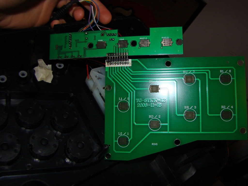
Here is the Top from from the Inside
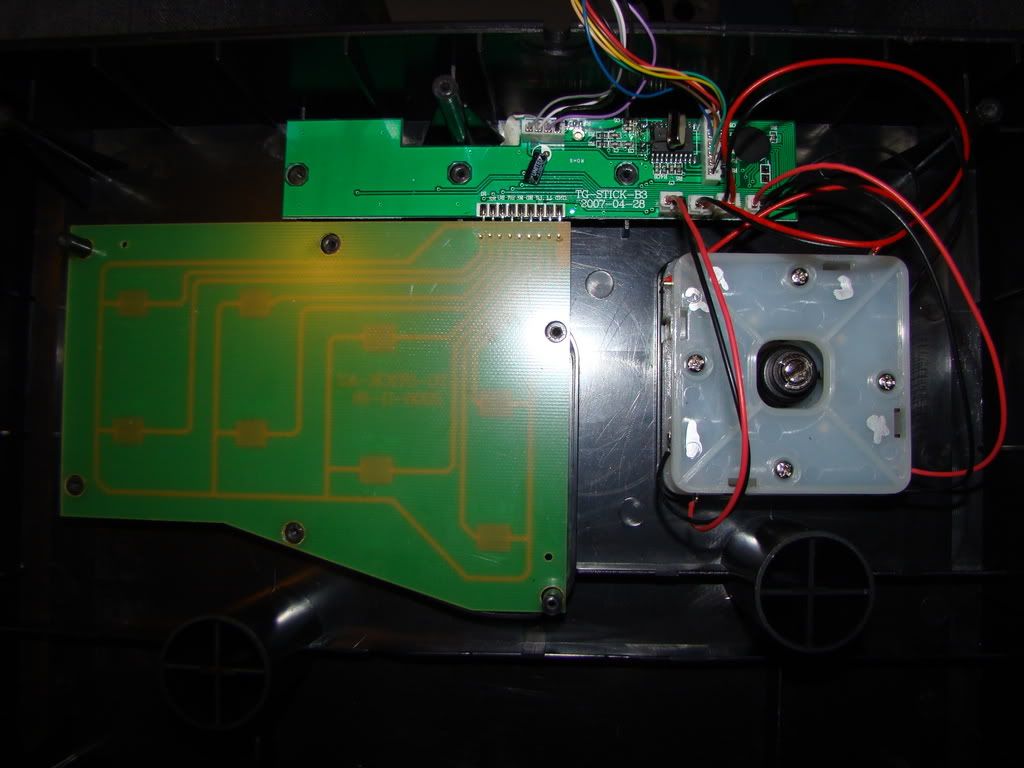
And here is the Underside
So here are my Questions about Wiring and modding
I should be removing the whole Bottom Circuit, unsolder that replace it with Microswitches to the PCB right?
Which ones are button 1-8 and is ground the one on the most left?(2nd picture)
If i want to change the Stick to a JLF, can i actually just unsolder the wires on this stick and resolder that on the new stick? (im not really sure about the mechanics of the stick)
Thanks in Advance
http://forums.shoryuken.com/showthread.php?t=132043&highlight=elecom
Remove the button pcb and wire straight to the solder points on the smaller pcb.
If you look closely at the solder points where the bigger button pcb joins the smaller one, it’s labelled L1, L2, R1, R2, BU(triangle), BD(X), BR(circle), BL(square).
In terms of numbering for standard SF games layout it turns out as 6,7,8 top row, 2,3,4 bottom row.
You’ll need to break the wiring on top of the jlf pcb first, I did this with a file. Then you can just solder the wires from the controller pcb to the jlf pcb.