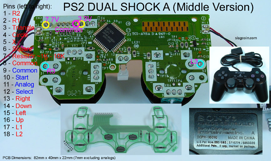
Your resistor must be soldered from 7 to 8 (since “resistor 1k~10k” line 7 is written in red, it must be linked to the common line of the same color (here “common” line 8 also written in red)).
It is said to avoid it because it’s difficult, yet not impossible. If you feel like you can do it, then go for it.
You only need 1 resistor ranging from 1000 to 10000 Ohms.
Just dont understand which pins are which… Some help plz… Really wanting to play some 3s… -___- Playin on a pad just a int doing it and I dont have money to dual mod.
Could someone tell me how Im suppose to wire this?
Seems like it will be easy enough. Just no clue which pins are which.
Also I know there hot and cold for each button… What about the other listed pins? How do I wire this?
Each signal must be linked to its corresponding common line. For example, the first pin labeled as R1 is written in red and must therefore be linked to the red common line located on pin 8. You will thus need 2 common lines (3 if you want R3 or L3).
As for the pins, top row (1,3,5,7,9,11,13,15,17) and bottom row (2,4,6,8,10,12,14,16,18).
A little bit different kind of pad hack:
Someone asked me about dual modding a [wired] 360 controller and I though, “sure, why not?” Well after investigating some I have a few answers why not, but that kind of makes me more interested, you know?
I think I’ve seen a dual mod done by replacing the PCB with a different (and smaller) 360 PCB, but I’m hoping to use the original, partly because one of the goals is to have the left analog stick still work.
So anyone done this? Anyone interested in kicking around ideas? Here’s what I’ve got so far.
The controller uses 1.8 V active-high signals, which is clearly no good, but I figure if I run everything through a suitable inverter to get 5 V active-low signals I’ll be set on that front. (Maybe it needs to be 3.3 V, but I’m targeting the Cerberus and from its chips data sheet I think 5 V should be ok. I should follow up with Phreakazoid.)
I confirmed Slagcoin’s pinout. Obviously I’ll have to use the test points on the back of the board so as not to interfere with the buttons. That’s a problem with the shoulder buttons, since their solder points are underneath the triggers, but I think I can solder to the contacts on the top of the switches and then sneak wires down below the board. The left/right pot on the analog stick has a similar problem. I might be able to hit the pins below the pot and above the board.
As far as dealing with the analogs, I’m thinking some comparators and a little voltage divider to get the threshold levels.
Finally, fitting everything is going to be tight. I was hoping to replace the rumble motors with circuits and keep the outside stock, but that may not be possible. If it’s not I guess I need to cut out the bottom and make a battery-pack-like protrusion.
Hey there guys, first post. Wanted to get some confirmation before I actually started padhacking my madcatz pad.
-
I have a madcatz #4716 pad with the year 2011 on the back with it. So i’m guessing this is the late version. Would the following diagram be correct for hooking everything (except the triggers) up with my arcade parts (sanwa JLF TP 8YT and OBSF-24)?
http://www.41thoughts.com/misc/srk/Madcat-4716-2007-PCB-wiring.jpg -
For the triggers, how am I supposed to go about this? Do I need to hex invert those? If yes, can some1 link me a diagram (can’t seem to find one at the moment).
-
For the wiring. Is it correct that I need 0.110 inch quick disconnects for the buttons? And what type of wire do I need? Somewhere between 22-26 awg? Stranded or full?
I think that that is all for now, thanks in advance.
Greetings from a noob padhacker!
XenoKronia
I think I tried .187 and it works, but .110 is the most snug fit. That’s why you’ll see .110s sold on eTokki, FocusAttack and with GodlikeControls/Toodles. 24 gauge seems to be the most common. As for Stranded vs. Solid:
[FONT=Helvetica]Hi there guys,
I got another quick question. In my previous post I asked about hex inverting a madcatz 4716 pad (year 2011 on the back) and I recieved a link to this thread (http://shoryuken.com/forum/index.ph…adcatz-4716-common-ground-xbox-360-pad.71804/). Now when I opened the case up, it said that the pcb was version E. In the thread mentioned, it states that verE doesn’t need hex inversion.
Now my question, if the triggers don’t need hex inversion, do I just hook them up like I would the other buttons? Do I use the trigger ground or can I daisy chain all buttons together to the same ground?
Thanks a bunch
XenoKronia[/FONT]
xenokronia: check the voltage between wiper and ground (wiper is central pin). If default is 0V (when no button is activated), you need to invert triggers, if not (you read 3.3 V or something), then you’re a lucky guy and can hook up those buttons like regular buttons. The ground should be the same for triggers and buttons (not difficult to check whether there’s 0 ohm between trigger ground and button ground)
If you’re positive the madcatz pad is from 2011, you will need to invert the triggers
Would it be safe to test this by desodering 1 trigger and then pluggin it in a computer to see if the input is the same as the still intact trigger? Don’t currently own a multimeter or anything of the sort.
As far as my knowledge of electronics goes, this doesn’t seem like it would cause any shortage. Ofcourse I could be wrong and destroy my laptop in the process 
I just got a PS1 digital pad H. Would my standard soldering iron tip be fine for this job or do I have to go and get a pencil thin tip?
Yes, depending on your skill with a soldering iron.
They weren’t kidding about the hot glue gun. I tried to solder to the H, and some of the copper contacts broke off and I had to throw away the pcb.I saved the cable for a MC Cthulhu one day. Next time I do this, I’ll apply the glue right after I solder to the point.
BTW. I tinned the wire and added solder to the pad. When I tried to combine the two, a few of the copper points (under the black stuff) just broke off. I clearly added to much heat. I was using a standard 30 watt iron.
Joytron / Datel Wild Fire Revolution for 360 & PS3
Less than 30 bucks online
hello guys,
i have an original microsoft xbox 360 controller, and an original sony ps3 controller, both are wired.
i’d like to have two mods; for the 360 controller, it should go like this:
back and start on the two analog buttons , and LEFT TRIGGER and LEFT BUTTON on LT, LB, BACK and START ( this way i can have 8 buttons on the pad and can use more buttons depending on the game).
same for the ps3 controller.
could anyone do that for me? is it possible? thanks guys
So you basically want the L3/R3 to be back/start and you want the back/start buttons to be LB/LT? And then the same thing for the ps3 pad?
For the 360 pad it would be relatively easy. On the ps3 pad I can’t exactly say because you mention an original sony pad, but sony never made a wired ps3 pad.
thx for the reply. i checked my ps3 original sony controller and on the back it says wireless controller so you are right, i thought it was wired because i see a usb cable on the top, i can remove it though. and yes, i want l3 r3 to be select start and back start , and then select/back start to be l1 l2 / lb lt
Wow… it’s been awhile since I’ve been on here, but alas I have a question!
So I completely desoldered everything on a madcatz pad and have it currently wired up to a ChimpSMD. Of course the PS3 side of things work, but the 360… it’s having problems.
I’m wondering if there a way I can wire a resistor or something to the nonexistent meters now. Hoping I don’t have to get another pad T_T
I’m almost positive this has been discussed before, but it’s been a lone time since I’ve been through here and I can’t find it. I’ve got a PS1 pad without analogue sticks padhacked, but it’s constantly sending out down+right signals, even without the directions being connected to the joystick. Is there a way to fix this?