no
The triggers need to be hacked the same as any other solder point.
But do they need to be inverted? Nein. That is the important thing.
yeah, that’s what i was looking for. thanks a lot guys.
Im going to try and padhack this: http://www.gametel.se/
Its a smartphone compatible pad, and it works with pc/mac aswell (HID-device using BT). I’ve extracted the PCB, and its really neat and small. It does not seem to be common ground, and i dont have a multimeter right now to try it with. The rubber dome contact area looks like the x360 pad, but with the copper exposed. I will post some photos as soon as i’ve started soldering it.
I’m not sure what i will do with it once its done, maybe a small phone stick for playing 3rd Strike on the go. Or maybe a small phone cabinet á la iCade.
Hi,
Fairly new to padhacking since I just learned to solder this month.
So I was able to wire up a working PSX and x360 pad.
Since I’m still new at this I would like to ask what’s going on in this scenario.
I wanted to have a dual mod stick even if it was just one case with two PCBs and two cords coming out of the body.
I connected the pads to a barrier strip and had them share the button wiring.
At first I thought it was alright since I tested the x360 pad and then checked the signals in windows…
THEN without disconnecting the x360 cable I plug in the PSX cable into the USB slot using a converter… it was working so I thought nothing was wrong.
Then later I tried the PSX pad without the x360 cable plugged in, I now see all the switches to be engaged…
Took out the ground wire that was from the x360 pcb in the barrier strip…
PSX wiring now works as expected.
really lost as to what to do now for this dual mod heh he.
Any advice would be most welcome
What are the golden rules of dual modding?
Just went through the guide again.
So I should connect the 3.3v on the PSX onto the 5V on the x360 pad and that should be it if I understand correcly?
Both pcb’s need their VCC and common GND point connected.
Do not plug in both PSX and 360 at the same time.
VCC is the one with the voltage indicated on the PCB diagrams correct?
so 3.3v for PSX and the 5v for x360?
Question though as they will be connected there, wouldn’t it create additional power draw on the PSX since it’s originally 3.3v?
I was wondering if that would fry PS2 controller ports, or this is something totally safe and should not worry about it.
Using a Microsoft x360 controller and Sony Ditial PSX pad btw.
Still confused if the x360 pad is common ground or not, I used a daisy chained ground wire so I believe it is.
Which x360 pads are not recommended for pad hacking?
Thanks in advance and sorry for the totally noobish questions having not read thoroughly all available documentation.
Just tried the x360 pad on an x360 and I was having some issues with the RT and LT.
I read that they should be set to neutral, so I believe I did.
Tested in windows controllers and the z-axis triggers right when I press the button wired to RT and then left when I press LT.
Now when I tested in UMVC3, what happens is that the button action is somehow “stuck” for about a second or 2 causing a raw tag twice instead of calling for an assist.
They shouldn’t be tied to the middle like analog sticks do, they have to be tied all of the way to the ‘unpressed’ voltage, with the potentiometer removed. Post up clearly what pad you’re dealing with and exactly what you did, preferably with pictures, and we should be able to be more specific.
MS pads are not common ground.
It is recommended to use a MadCatz 360 Fightpad / Brawlpad / Strekken.
Desolder the cable you want to swap, then use a screwdriver tester or something similar to check out to what pin of the plug each wire leads to (for ex: green leads to pin 3). Once you did that, repeat on the cable you want to install.
Here are the images of what I have done so far
http://i862.photobucket.com/albums/ab184/shir0kami/Stick%20modding/P1040849.jpg
Really messy wiring, thoughts on dual mod possibility
http://i862.photobucket.com/albums/ab184/shir0kami/Stick%20modding/P1040866.jpg
MS x360 pad, Pardon the soldering work and glue
http://i862.photobucket.com/albums/ab184/shir0kami/Stick%20modding/P1040869.jpg
not sure if it’s visible but this is the left trigger and I turned the potentiometer all the way to the left.
http://i862.photobucket.com/albums/ab184/shir0kami/Stick%20modding/P1040871.jpg
Triggered RT with the ground wire close the “Y”
http://i862.photobucket.com/albums/ab184/shir0kami/Stick%20modding/P1040870.jpg
did the same with LT
http://i862.photobucket.com/albums/ab184/shir0kami/Stick%20modding/P1040864.jpg
RT using button
http://i862.photobucket.com/albums/ab184/shir0kami/Stick%20modding/P1040865.jpg
LT using button
I just tried this on kawaks using joy2key and I had no lag issues with the triggers…
Strange that it was acting up on the x360, or am I missing something?
So the MS Pad isn’t common ground?
Then what’s with the diagrams I saw on slagcoin? That had me confused
I guess I’ll just put the PSX pcb or this x360 pad in another box one of these days
I got these cheap btw so I wasn’t really scared of breaking them haha
Cost me roughly $5 for the digital pad and $7 for a “broken” x360 pad because of a faulty LB.
The MCZ digital pads are rather expensive here… they cost roughly $50-$60, used ones are selling for around $20.
At least I learned to solder although not that clean yet.
Thanks for responses.
I might just get a custom PCB one of these days for a dual/multi mod.
I’m almost done solder my hori V3-SA, but can i solder on the back of the hori board to connect the ground to the V3 board. Also if there is someone who has dual modded a hori arcade pro V3-SA to a leo V2 can i can they putt out some good pics of it.
Does anybody have any experience with hacking the wired PS2 Katana-branded controllers? I took it apart once, and the insides were a lot like a cheapo PS1 pad. Is it common ground?
So i got myself a cheap multimeter, but it doesnt got a continuity check function. It got the diod check and it got the ohm test, and i think ive read som where that you can test for continuity with the ohm-tester. I tested it with the Ohm-test, and i figured that if the points on the PCB are connected somehow i will get a reading. I get 700 ohm when i put the mulitmeter at both sides of the rubber-dome contact area. But when i switch places on the red and black tips i get nothing. And i get 700 ohm from one side of all the other rubber-dome contact areas aswell. So i think its common ground but im not sure.
Im i doing it right? And will the 700 ohm of resistance be a problem if i solder it as a common ground? If they add up or something?
EDIT: Okay, so i tried some other spots on the pcb, and there it says 1 ohm. It seems like i get 0-1 ohm from one side and 700 the other.
EDIT2: Made a little video, since it was kinda hard to explain 
[media=youtube]cGselEAl0X8[/media]
ok i got a problem with my mod that i did about a month ago, well its not a problem more of an annoyance. i have a pad hacked 360 brawlpad inside my PS3 StF4 SE stick connected threw a switch so i can switch between PS3 and 360 when i want. my problem that i have is than when i switch from PS3 to 360 the turbo panel on the stick lights up and starts setting the buttons to turbo every time i hit a button. my question is how can i fix this so that when i switch to 360 mode the turbo panel wont turn on with every button pushed?
- Side note: all i have pad hacked on the brawlpad is all the buttons execpt for the home, turbo, and the switch for switching between Left/Right stick and D-pad.
Which slagcoin diagram corresponds to the GameStop ps2 controller? How easy is this pcb to padhack? If it is difficult, can someone refer me to a modded on the east coast that I can send the controller to and has it padhacked for a fair price?
Hello, im gonna start a pad hack with this PS1 Pad
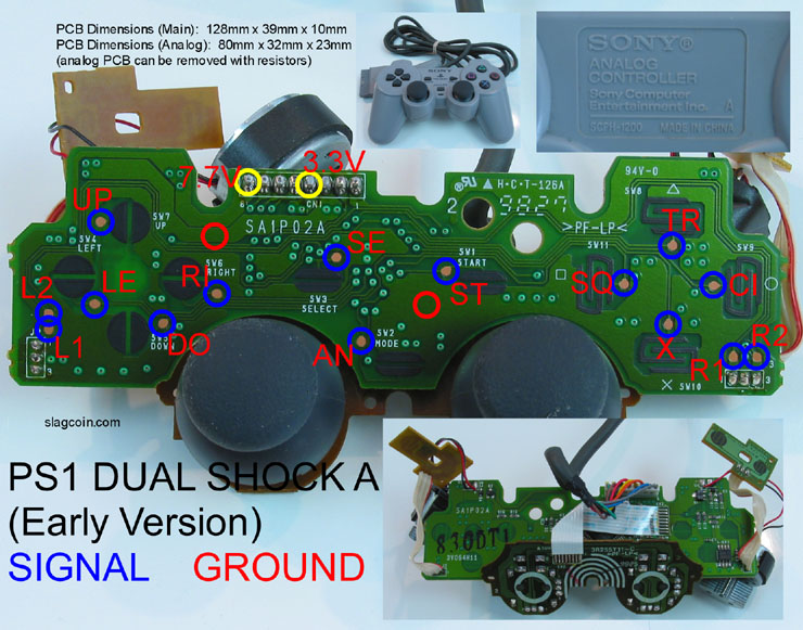
I kinda get where to solder most of the signals, but I just have a few things that confuses me, the ground points are in blank spots in the board, what exactly am i supposed to do there? peace.