If you do not know what to do, then just solder two wires per input for the Arcade Stick.
You see two halves for each input on the Mad Catz PCB.
Solder a wire to each half.
The Triggers will not be that simple though.
If you do not know what to do, then just solder two wires per input for the Arcade Stick.
You see two halves for each input on the Mad Catz PCB.
Solder a wire to each half.
The Triggers will not be that simple though.
That much is obvious. I was just looking for a pinout.
[FONT=Helvetica]I have the PDP afterglow for the XBox 360 and I beleve it’s a common ground though I’m having a hard time dual modding it with my PS3 HRAP3.[/FONT]
[FONT=Helvetica]When the DPDT switch is switched to the XBox, the following occurs:[/FONT]
[LIST]
[][FONT=Helvetica][FONT=Helvetica][FONT=Helvetica]the signal for Left on the XBox PCB is 3.3V[/FONT][/FONT][/FONT]
[][FONT=Helvetica]the signal for Left on the PS3 PCB is 3.3V[/FONT]
[/LIST]
So if both Left signals are connected (i.e piggybacking) it will be 3.3V and pulling the joystick left will ground it sending the left signal.
http://img69.imageshack.us/img69/9140/15022012135.jpg
[FONT=Helvetica]Now this is where I don’t understand…[/FONT]
When the DPDT switch is switched to the PS3, the following occurs:
[LIST]
[][FONT=Helvetica][FONT=Helvetica][FONT=Helvetica]the signal for Left on the XBox PCB is 0V[/FONT][/FONT][/FONT]
[][FONT=Helvetica][FONT=Helvetica][FONT=Helvetica][FONT=Helvetica][FONT=Helvetica][FONT=Helvetica]the signal for Left on the PS3 PCB is 3.3V[/FONT][/FONT][/FONT][/FONT][/FONT][/FONT]
[/LIST]
[FONT=Helvetica]So if both Left signals are connected it will be 0V (grounded) and pulling the joystick left will have no effect as it is already grounded, hence the left signal is continuously sent.[/FONT]
[FONT=Helvetica]
http://img850.imageshack.us/img850/6178/15022012136.jpg
[/FONT]
[FONT=Helvetica][FONT=Calibri][FONT=Helvetica]Anyone with feedback or ideas?[/FONT][/FONT][/FONT]
[FONT=Helvetica][FONT=Calibri][FONT=Helvetica]Edit: SOlved it by wiring up a push button from USB data - (green) to the thrid pin on the horizontal connections to the right of the bottom analog stick[/FONT][/FONT][/FONT]
Boita-carton, post: 6140624, member: 51404
I plan to dual mod my ps3 TE. First step is to packhack a xbox360 pad. I hope this hasn’t been already asked, but what is the best pad model you guys can advise me ? If it’s possible, an easy to solder and one which I don’t need to invert the triggers. Also I would like to use the 8 attack buttons on my stick. Otherwise can I just pick a wired 360 pad at my nearest shop ? I’m totaly new to soldering and this will be my 1st mod apart modding my TE into an hitbox 
An update on my dualmod.
I just wanted to share my joy of padhacking  I have to say it’s a nice experience, it’s the first time soldering for me. But man the attacks buttons weren’t easy. I shorted at first the X, LB and guide buttons, but I managed to push the solder away from the grounds.


Then for testing, I stuffed all inside my case, and did the solderless method by inserting the wires into the sanwas tabs. Everything works fine so far, xbox and ps3 side.
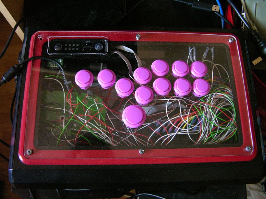
Look at this salad of long wires This is only temporary for testing. I don’t want to keep that usb cable like that
Next step is to solder the SOCD cleaner with my wires since the SOCD is different from xbox/ps3. And the last step is the Impv2.
heres a question to something that i just noticed. how come the 360 StF X Tekken pad button layout differs from the 360 WWE Brawl pad?
and by differs i mean why are are the R’s and L’s in different locations. just been buggin me lately.
Something to do with the default game config in WWE Brawl. Brawlpads also have a quick R Stick mode which is not necessary for something like Strekken.
Strictly the art.
ok so if i was goin to pad hack one to do a dual mod, which one would be best to use even thou they are both pretty much the same wit just the L’s and R’s in different locations.
You answered your own question - they are essentially the same.
Solution: get which ever is cheapest out of a Fightpad, Brawlpad, or Strekken.
tru ok thanks, i guess im goin with the Brawl pad cause its 20 bucks compared to the sfXtekken which is like 40 bucks if i remember correctly.
Yep, Brawlpads are certainly cheap at the moment.
Okay so I have been thinking about dual modding my PS3 SE fight stick with a 360 Street Fighter pad hooked up to a DPDT switch. This is the wire layout that i got so far and not sure if it will work, so i was hoping to see if any one can help and see if they think this would work as is or would need to be missed with a bit.
http://i1255.photobucket.com/albums/hh623/DeGlitch/Layout.jpg
Yes.
quick question, if i solder a wire goin from the Guide signal on the pad to the Home signal on the stick, and the Turbo signal on the pad to the Turbo signal on the stick, would the Guide and Turbo function work when I press the buttons on the stick when in 360 mode?
Thanks
Yes.
Well than i guess i better get the old wheels turning so i can push this out before nxt Sat.
Hi there, I have gotten my hands on a newer dualshock 3 controller. There is no port where the plastic part would go in for the buttons. I think I know where to solder the buttons, but I got no idea where to solder the resistors for the L2 and R2 buttons. I could take pictures of the PCB and make some kind of wiring diagram and post here so you all can see the PCB. Or if someone pad hacked this kind of PCB before, maybe he/she can help me with where to place the resistors?
Thanks anyway!
So this is what I have so far on my Dualshock 3. If this is wrong, please help me out. Thanks
http://dl.dropbox.com/u/41248345/PCB%20sub%20with%20annotations%20V1.0.jpg
http://dl.dropbox.com/u/41248345/PCB%20main%20front%20with%20annotations%20V1.0.jpg
the first picture you have correct. the second one does not show the other side of the double sided PCB or the wires that go out of the picture to the R1/R2/L1/L2 daughter boards. however, you can clearly see that what you have labeled L2 is correct cause it runs down to the silkscreened letters that show the corresponding pad as L2. the L1 pad silkscreen label is right next to L2 silkscreen. follow the trace till it pops through that hole and flip the board over to find that same hole. there should be a trace there to confirm the location of your L1 within the J1 3pin header. R1/R2 should have a similar symmetry but it may or may not be mirrored to L1/L2. I find it odd that they have only 3 pins total to something that has one button and one analog. if the analog is a voltage divider, it has a fixed resistor on the main board. the other theory is that the analog triggers are part of some current dependent sensor. but I’m leaning towards voltage divider with a fixed resistor. so what would be the ideal setup for pullup and variable? 1k fixed pullup and 5k pot? this would give you 0v to +3.08v. with the controller on, test your DC voltages. with your controller off, test for resistance (Ohms). also test your triggers for resistance when depressed and not depressed. if your trigger reads 0Ohms when pressed, you are good to wire up a button. no resistor needed. if your trigger reads 0Ohms when not depressed then its a  for now.
Anybody have the xbox 360 afterglow controller diagram