Single format pcb = Mad Catz 360 Fightpad. You should consider using either a DPDT switch or an IMP board as well.
Personally, I’m eagerly awaiting the PS360+ board from AkihabaraShop, but there’s still been no updates on this for a long time…
Single format pcb = Mad Catz 360 Fightpad. You should consider using either a DPDT switch or an IMP board as well.
Personally, I’m eagerly awaiting the PS360+ board from AkihabaraShop, but there’s still been no updates on this for a long time…
Thanks for the answer! So is this the right fightpad, will I be okay ? Nothing to worry about the triggers ? And yes I’m waiting too for the PS360+ and buy an Hitbox but I don’t want to miss another tournament in my area. I’m also planing to go with an IMP board and a SOCD cleaning kit.
Yep, that one though you can probably find them cheaper. A used one should do you fine.
No complicated trigger hacking necessary, just as the gods intended. Solder and go.
I just wanted to inform everyone the hex trigger method used for late 4716 madcatz works like a charm for the HORI ex2 pad as well
I ordered the itsy bitsy 74HCT smd hex by accident but it still works great
go for the brawl pad if you have gamestop locally its only $20 works the same way as the SFIV fight pad
quick question, since i have a PS3/PC PCB and i hack a brawl pad for use on a 360 will i need to use the cable running off the pad itself or can i cut that off and just use the USB jack that runs off the PCB?
I dont cut the cable off directly I give it 6inch to or so and I remove the rubber sheath to have the r,g,w and black wires loose to connect to the imp or whatever you are connecting to
My friend gave me his broken sony ps3 controller I was hoping I could make use of the axisdapter lying around. When I opened it I noticed there it didn’t have the ribbon terminal. I searched around and found these nice scans of the pcb I have (model MSU_VX4). Does anyone have any experience working with these pcbs? If so, how would I go about the wiring in the 2nd picture since I read that I need to use 7.5k resistors?


[LEFT][/LEFT]
[LEFT]Hey, [/LEFT]
[LEFT] [/LEFT]
[LEFT]I have PSX pcb’s from those twin stick controllers, at the moment when i plug it in to the pc and push a button. X and Y rotation is set to full and down fwd is engaged in the X/Y axis. all buttons and pov directions work as normal. did these pcbs have a switch that must be disengaged so that only pov direction and buttons are used? I have wired up the 2nd pcb and the same result so i believe something is engaged on the pad. I have only ever had these pcb not the actual stick so I don’t know what components or how it was wired. [/LEFT]
[LEFT] [/LEFT]
[LEFT] [/LEFT]
[LEFT]Does anyone have experience with these pcb’s?[/LEFT]
[LEFT] [/LEFT]
[LEFT]psx pcb pic:[/LEFT]
[LEFT]http://localhostr.com/file/rAWDT77/DSC01826.JPG[/LEFT]
[LEFT] [/LEFT]
[LEFT]reverse of the pcb:[/LEFT]
[LEFT] [/LEFT]
http://localhostr.com/file/RVIs4Zt/pcb_reverse.jpg
Do you have a picture of this twin stick? what adapter did you use to plug it into the pc
regoogled but just did image search this time as i couldnt find it last night. The original psx stick is the playstation 1 skream twin arcade stick. the adapter used is ps2 to 360 adapter
like the one etokki sells but all black.

Hello all,
I am trying to figure out what I need to padhack a PS2 pad into an arcade stick. I can understand the idea of ‘common ground’, and some pad PCBs have two sets of grounds, one for select/start/etc and one ground for the rest of the buttons.
What I can’t figure out is where I connect the resistors to, and which ones I will need, for example, this is a diagram from slagcoin :

Does this mean I connect a resistor (1K to 10K ohms) to pin 7 and the (red) common ground?
Thanks in advance.
Dont worry with the resistors have you read the main page on slagcoin about pcb wiring
the resisters are on the membrain
Oh…hrmn…yes, I came across a picture with resistors soldered onto the pins and I guess that was to illustrate what you needed to do if you wanted to remove the membrane.
Thanks for the clarification 
Hi people, I have 2 questions:
A friend of mine burned the start trace on a TE 360 pcb, I wonder where I can get another point of start signal on pcb?
another question, I’ve done a dual mod on Xbox360 TE with a dual strike, just soldered the 2 pcbs with a piggyback conector and all worked well, this time I want to do something similar in my custom, but with a padhack and have the following doubts, I have to connect the buttons and joystick to the 360 pcb or I can connect them directly to the dual strike?
P.S sorry for my bad english:oops:
Is there just like, a basic tutorial blog/video hanging out there on making a stick out of a MC fight/brawlpad? I understand the basics of the process but an actual walkthrough would be sweet.
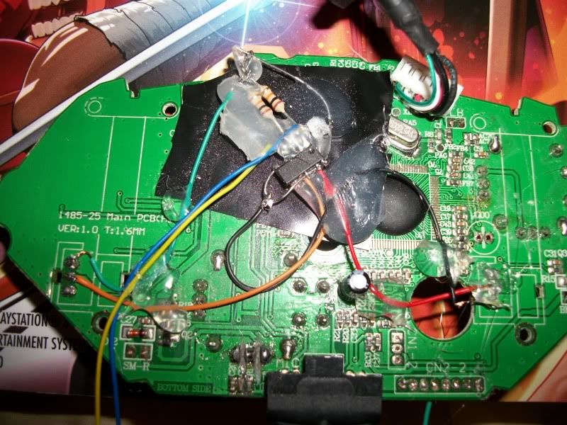
I need some help with the RT, it behaves like it’s constantly being pressed. I removed the pots and made an inverter chip using Toodles’ guide. LT and RT are both wired into the chip but only RT is used since it’s a 6 button 360 only stick.
So my questions are:
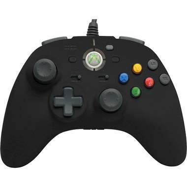
First off I’m using this pad.

Here is the completed mod.


Wire layout for inverter from top to bottom.
Blue = Low
Red = Right Wiper
Red = Left Wiper
Blue = High
On the pad in the pic about you can see the 3 spots of the pots under the orange wire. Going from to button the layout is:
top = low
middle = wiper
Bottom = High
Are these correct?
It is still salvageable. Follow the trace from where the guide button was to that small circle pad that is now gone. If you carefully scrape away the green coating above where the small circle was it should uncover the copper trace for the guide button. The trace goes up and to the left right above the Player 1 green LED. The trace is really really narrow but you should be able to use the pad from the Player 1 LED to reinforce the your solder on that tiny tiny trace. Hot glue it in place as soon as you solder it so you don’t rip the trace out with the wire you just soldered to it.
Hello.
I’m interested in buying this gamepad (Hori EX2 turbo) and use it on Windows7 Ultimate 64.
Does it have any driver issue?
Is it 100% plug and play?
Does it work with MAME, Project 64 and Dolphin emulators?
Thanks. Waiting for answers.
Re-up.
I think this is the best place to make this question about usb cables and padhacking.
I have a padhacking on a Thrustmaster Firestorm Dual Analog 2:

I want to change the usb cord, unsolder it from the pcb and solder a new one with a female end like this one:
http://www.ocp.com/product_search/images/products/photos/71032.jpg
or

The question is about the colors on the cable.
http://oranges-world.com/data_images/usb-cable-wiring.jpg
Is this always the correct order both for male and female cables.
This is my pad PCB:
http://imageshack.us/f/8/p8210010.jpg/
If I unsolder the usb cables, and solder the new ones in the same places and same color, will it work?