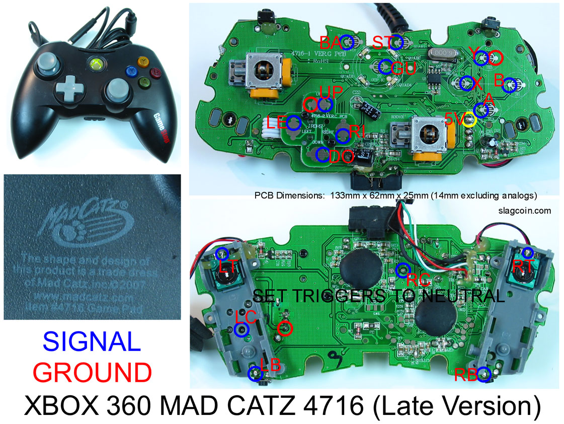
The top clicky buttons are LB on the left and LT on the right. If you look closely you can see RB and RT in the picture above, they’re kinda hard to see because the text is in gray but they’re there. As for the solder point for Guide, I’m not sure where the S12 point is, but as long as you solder to the top half of the metal contact it should work. I think there’s a little dot that should be easier to solder to just like the other buttons.
Hey all,
First time padhack attempt here, with a Dualshock 3 MSU_V3.5X 1.12 board. Home/start/select works, but all the other buttons (down, left, /, [ ], O, X) seem to register as “always on” and don’t respond to the button presses. Anyone have any ideas on what could be the problem?
EDIT: temporary fix is that i reattach the membrane from the dualshock 3 and it… works? Not sure why!
hi i’ve been wanting to get my tvc stick padhacked so i bought a gamestop brand 360 controller to dual mod with. i’ve soldered signal wires to the 360 pcb, but i’m confused on what to do next.
the membrane has a resistor on it (and i think for the PS3, it has 2)
you either solder the other end to the buttons, or you add QDs on them and put them on the buttons
the buttons are already QDd onto the wii pcb. would i still solder the other end of the wires to the prongs on the buttons?
What’s a good way to get rid of the membrane then?
saphier: http://slagcoin.com/joystick/pcb_wiring.html
Look for the model, read the whole page.
gerikuso: Uh im a bit confused. I’m going to guess that you have the pcb soldered properly. In which case on the other end of the wires going to the buttons and joystick, either solder or use QDs(.110) if you need more info try this page, http://slagcoin.com/joystick/example2.html
Thank you! Mystery solved 
EDIT: After putting the resistors onto the back of the daughterboard interface, home button is stuck to always on :. Before I tinker with it more - I wonder if it’s because the resistor may be overlapping the PS Button pinout?
http://img851.imageshack.us/img851/554/dscn77481.jpg
http://img534.imageshack.us/img534/3741/dscn77491.jpg
this is how i soldered wires onto the 360 pcb. signal wires are on all the signal sides but only some ground sides have wires on them. what shall i do now?
You don’t have Power connect to Power?
You have the UP wrong.
The Ground and Signal is switched.
Unless you switched the colors is all?
[LEFT]
im kinda confused on which part of the usb wires/wii wires are the power wires so that i can connect.[/LEFT]
USB is Red.
You have to test what Wii is.
Because not every manufacture use same color.
so green and black are data? sorry if im asking too many questions. i didnt really see any tutorial on finding power and stuff.
how would i test the wii wires?
i was following this picture http://slagcoin.com/joystick/pcb_diagrams/360_diagram3.jpg. if the up is wrong, are all the other wires correct? (red is signal, black is ground)
You followed that?
How did you get Start correct then?
This is the correct one for yours.
http://www.damn-son.com/upas/frontlabeledcopy%20copy.jpg
The slagcoin one is for old year, 2007.
You need the 2008, 2009, 2010, 2011 diagram.
haha, for start, we looked at the pattern of the sides that signal was soldered onto and followed that for start, since it was different.
ok so after soldering on the correct places on the 360 pcb, do i just connect the other ends of the signal wires to the wii pcb?
Thrustmaster T-Wireless padhack.
More pics at: Check Out My New Arcade Stick!
http://img543.imageshack.us/img543/5472/twirelesspadhack.jpg
So I got this new Madcatz 360 controller so I could dual mod my stick since I burned out the old one (don’t ask).
But when I took it apart, the PCB is much different than what I had.
http://img825.imageshack.us/img825/5232/img0043lk.jpg
Is this common ground? Or should I just go trade my friend for his controller?
The serial in the top right reads:
100.009.001.2382
MOV47161 Rev.A
2011-04-02
Thanks for the help, all!
EDIT: Just saw gerikuso is using the same PCB as I am… is it still the same signals/grounds?
Picture I posted.
Rgr!
Thanks jdm! Will report back later on today!