Should work fine. Since you’re not dual-modding, common ground doesn’t matter.
Looks cheap enough that the PCB probably won’t be sophisticated, or rather the PCB will utilize circuits that are dead-simple to read and work with. If all else fails, just post a photo here.
Hi all, first i would like to say that its 1am here and i don’t have the time to be going through 86 pages of this thread to find what i’m looking for, so i apologize ahead of time. I have this pcb: http://slagcoin.com/joystick/pcb_diagrams/360_diagram2.jpg and i wanted to know how to set the triggers to “neutral” i noticed that on other pads you need a chip of some sort and two resistors. Do i need that stiff for this pcb as well?
Pull those black switches off at the triggers, connect a resistor to the top and middle contacts, then wire your button to the middle contact.
so there are 3 contacts under the black trigger switches? What type of resistor should i use? I need two resistors right?
so im thinking of padhacking a madcatz pcb for my simple case and i just want to get some things clear so there are 5 different wires that are connected to the pcb sorry i dont have a pic. a red 5v,white d-,a green d+,and 2 black ground my question is do i need both ground wires because im thinking of having a Neutrik NAUSB-W-B A/B USB Feed-through on my case and i want to cut the cable to about a ft. so i wont have the 10 ft cable in the case all tangled up and stuff. sorry if this doesnt make much sense im a noob
Quick question on Playstation 1 Digital Philippines pad. The copper has been stripped away on the R1 solder point so it doesn’t accept any solder anymore.
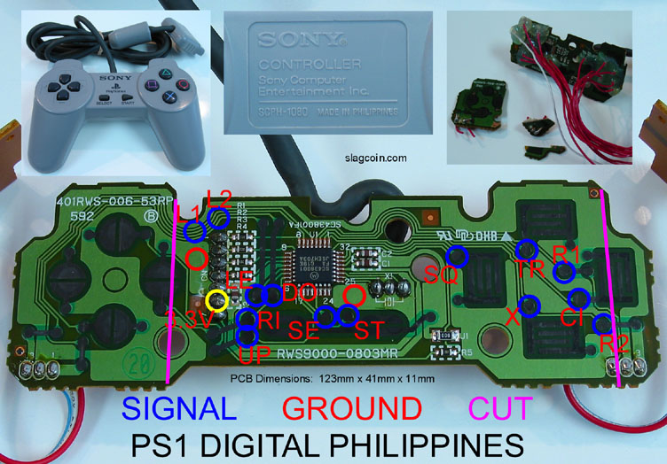
Does anyone know how I can expose the copper for L1 on this pcb so that I can solder the wire to the button?

Ah thank you. I will try this when I get back home. Just a quick question, would this mean that there are two signals for the R1 and R2?
There aren’t two, they’re connected on the same line. Slagcoin just used to show you where you could do them in the most compact way so that you could cut the pcb down to be smaller if you needed it that way.
Okay, so I decided to change my HRAP EX PCB into a cheap USB controller pcb (it works on a ps3) since CHIMPSMD is out of stock :’(
So, Can I use the original Xbox 360 USB cable instead of the cheap usb cable that comes with the controller PCB ?
The problem is that the xbox cable has 5 wires, while the USB controller cable has 4 wires!
Edit :- Found out that the grey is Shielded ground, and not necessary 
Hi guys would anyone be able to tell me the location of RC and LC on this pcb (4716 rev E) and would
i be able to use these instead of triggers for a eight button set up
http://www.damn-son.com/upas/frontlabeledcopy%20copy.jpg
http://img189.imageshack.us/i/backlabeled.jpg/

You can’t even use LC and RC in Fighting Games.
So how would that work?
I’m play super streetfight iv on the pc and can map those buttons to any action
with the controller. Do consoles not have this option?
Oh, I didn’t know PC can do that.
Console does not do.

hi can anyone help me?
i accidentally burned thru the contact for RT… does anybody know an alternate route?
also i had the LT working but then when i burnt thru RT it also stopped working…
any suggestions? thanks in advance…
Okay i’m a little bit confused here and could need some help. I’m new to all this padhacking-thing so please appologize if the question has been answerd before. So I’ organized myself a madcatz fightpad se. But somehow I can’t find any real good diagrams. If someone would be so nice to post them. I already found some but they’re all a bit diffrent and now I don’t know which one to use.
Many thanks in advance
Jubei
madcatz fightpad SE?
or do you mean the xbox 360 madcatz fightpad streetfighter edition… because if it is the xbox 360 fightpad you are looking for the pic is above your post…
You’re right I mean the one above, but I can’t see LT / RT there and also can’t identify the solderpoint for “Guide” Do I have to solder the Ring or the S12 Point ?
anyone have a nubytech ps2 SF pad? I tore the cable from the pcb and can’t figure out what color goes where. does not match up with default color layout.