I think I found that thread, thanks!
Here ya go… I have enough to last a bit. I dont see 4716 any cheaper unless its on ebay used.
Buy.com - Official Street Fighter IV FightPad Controller for Xbox 360 - Chun-Li
Yeah, that’s a good deal. The 4716 pads are 19.99 at gamestop stores used, while the fight pads are 24-29.99.
I will probably pick up a couple of those, because that’s the lowest I’ve seen them.
Hello all, trying to build my first arcade stick and had a couple of questions. I had 2 controllers donated to me, a wireless xb360 (official controller, common ground) and a corded xb360 (official controller, not common ground) I have read while going through the forums that common ground is much easier for soldering but I don’t want to use rechargeable batteries. Is there a way to connect a USB cable to a wireless controller to get power to it?
P.S. I have already exracted the PCBs and cannot attach the batterypack onto it.
If you don’t plan on dual modding, you can just use the non-common ground PCB by itself. Just solder wires to both sides of the buttons, and then connect both sides to the button that you want it connected to. It’s not harder to solder, just easier to wire common ground.
However, for the joystick, you may want to get a JLF-TM or a plain LS-32, not a JLF-TP or any Seimitsu stick ending in -01. Then connect one side of the direction to COM, and the other side to N.O. N.C. will not be used. JLF-TP and LS-32-01 are designed for common ground PCBs, and so it’d be much easier to use an LS-32 or JLF-TM.
Thanks for the quick reply, wish I knew that before I ordered the JLF-TP, lol. You know what they say about hind sight… I suppose I will have to modify the sanwa pcb to work on non-common ground, anyone know where I can find out how and where to cut and resolder the traces?
This should cover it (Ignore the bit about the EX PCB, it’s just another non-common ground PCB)
Connect to the microswitches after you cut the traces:
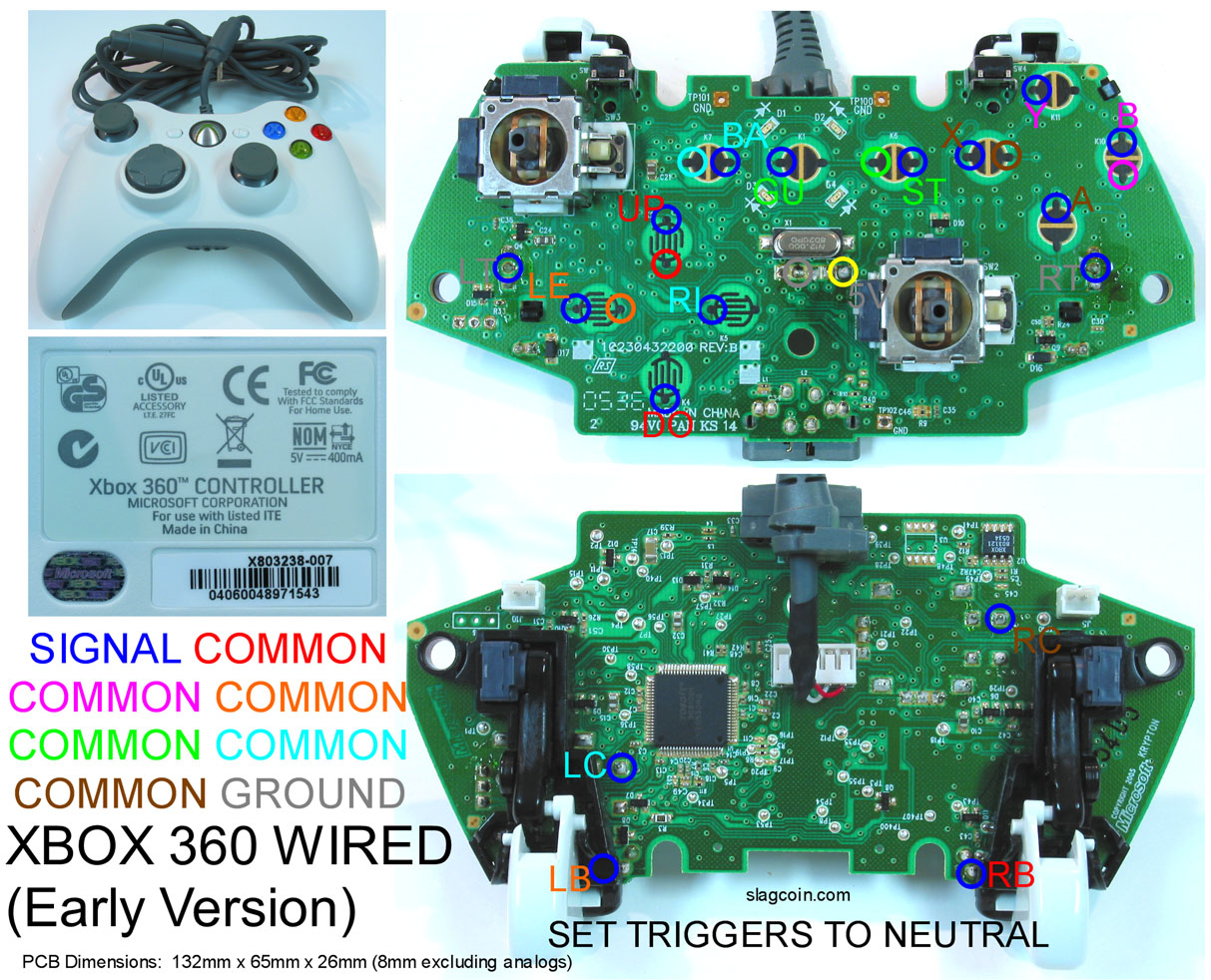
This thread has been super informative and everything but i have yet to find an answer to this question. Does anyone have a close up shot of exactly where the solder points on a XB360 Wired early version. Ive herd i need to cut away some of the plastic that makes up the trigger? and why would i need the Right and Left Click buttons? i dont think i should even bother soldering them.
I think you only need to cut away plastic if you plan on not using the trigger buttons…
[media=youtube]bXkUo090ffY[/media]
Nice video working with a Wired early controller 
oh, yea if im making a 6 button fight stick i dont need RT LT and RB LB. duh 
So if i understand correctly, there are 8 wires coming off of the D pad and 8 coming off the ABXY buttons. Correct me if im wrong but 8 of those are signal and 8 of them are common (4 of each for the D pad 4 for the ABXY buttons)? In the youtube video he has 2 wires coming off every button but in Slagcoins pictures the A,X,Right and Down contacts only have one circle. An explanation would be great.
And this might be a handy piece of information for everyone but do any of you recommend any simple electronic books? Maybe one of the Dummies or even a high school/college level book. I need to get my signals, commons and grounds straight lol
Here’s how it works. With a common ground PCB, each side of the buttons are signal and ground, in a common line PCB, there are common lines that have like voltages, here’s a picture to demonstrate:

When the signal is either connected to ground (common ground), or connected to the common line (non common ground), then the chip (Integrated circuit or IC for short) reads this change, and then knows to tell the system that the button is pressed down (Buttons are simple switches that just connect two things together).
Here’s how they might look wired in a stick:
In that picture, the joystick shares a common line between the four directions, and none of the buttons have a common.
Now, these different colored commons in the slagcoin diagram represent different voltages. Take X for example, its letter is brown (but it is a signal, so that side is circled in blue), so it needs to touch a brown common in order for the PCB to tell that X is being pushed down. Now, you can see there is a brown circle next to X, because every button has its common on the other side of the signal (Because pushing a button in a controller connects the two that are next to each other, and you always want the common that it should always touch next to it)
Now, look at A, it is also brown. That means the other side of the blue circle for the signal of A is also a brown common. Now, what you could do to reduce wires from the PCB is to take just one brown common, and connect that single wire to both buttons (via daisy chaining, barrier strip, soldering two wires to the same common, whatever).
That is why the video only has two wires, it opts to share the common.
Why I told you to solder to both sides and just connect both sides of the button is because the signal and the common it needs are ALWAYS next to each other, so you don’t have to worry about which common goes to what.
Also, dpad directionals are the exact same as buttons. The only difference is that dpad works on a circular pad instead of buttons. But again, just connect one side to COM, and the other to N.O. (You could connect commons to COM, but like I said, it’s just 10 times easier to solder a wire to both sides and just connect them to their respective buttons or directions).
I hope that helps. I don’t know of any books. I just kind of picked up everything going along.
So for the early wired 360 model im treating it like a Non Common Ground PCB? and for wiring it to the Joystick PCB do i need to cut those lines? if so where can i get a hi res photo i dont want to cut the wrong ones. i already got one cut, but dont want to risk cutting the other ones wrong its hard to tell in the video.
All official microsoft pads are non common.
And they’re also all a total pain in the ass. If you have the means I highly recommend just grabbing a madcatz pad for $20 at gamestop.
Especially if this is one of your first times doing a project like this.
I thought i just successfully did the madcatz retro pcb trigger hack using the 10k resister to the 3.3v and wiper for both LT and RT. Z-axis positive and negative fires when pressed on my pc. When i plugged it in to the 360, nothing. if you are looking at it top down i have it wired like;
    ___o                           o__
{10k}__o______>  to button <_______o__{10k}
       o                           o
I get a signal tone from the button to the wiper( the middle solder point)
what else should i test for/check or what could have gone wrong?
can anyone help me with this please.
The only official pad I have ever enjoyed hacking was the OG digital PS1 controller pre-dual analog controller. 6ft+ long cord and 1 ground + decent sized contacts.
Okay I have a question, what is the consensus on the PS360 from Akishop? I am about to rewire my agetec and a 1 ground 3 system solution sounds pretty nice because I won’t have to rewire anything. I just want the good and the bad and if it is worth the money or if I should go another route for my case. I just want to know if it has any lag issues or any problems like that.
Few more questions…
1.) There are two wires coming off my PCB going to my button. Does the wire to button contact matter? or just stick it on any of the contact hanging down. if theres a difference how do i find out?
2.) I have 2 wires coming off my PCB DPad for each direction. Where do those go exactly? I assume they connect to my harness or i’ll wire them straight on to the contact where the harness attaches. And my harness is all black wires so i dont know which one is down, up or whathaveyou. I know i saw a diagram somewhere about which contact was what signal but i cant seem to find it again.
Hello
I need to hack this Genius USB G-08X2 pad. From my very limited padhacking knowledge, I see that this pad is fully common ground, am I right? If so, can you guys please point me on where I should solder each cable? I have an idea, but I fear that I might screw this.


Thanks in advance
Yes, it’s common ground.
Those little circles beside each button spot are perfect, I would go with those for your directions/buttons.
For the LT/RT type buttons, you want to use the spot that has the trace leading from it (the little lines running to the button ).
For the ground, you can either use the other side of any of those copper button spots, or you can scrape away any of that big green that’s around the middle and expose some copper underneath.
-
doesn’t matter which contact on the button.
-
If you have a harness you will have to solder straight to the switches, or cut the traces on the pcb on your stick.
Like I said before, non-common ground pcbs don’t play nice with a lot of sticks. A JLF wire harness is set up to be used with a common ground pcb (one ground, 4 directions).
Thanks Lucky!