I know you can cut a good inch and a half on both bottom sides of the fightpad pcb but I dont think you can cut it down to a paewang sized board. the bottom left and right can be cut completley but you just gotta watch out for the traces in the bottom center… I’m too lazy to follow all the traces to resolder those so I have never tried it haha.
Browsing DealExtreme trying to find Blaze 2P stick for PS1/DC and saw this;
Desc: Designer’s Wired Game Controller for PS3 - Black (160CM-Cable)
Price: $9.80 + Free shipping

DealExtreme: $9.80 Designer’s Wired Game Controller for PS3 - Black (160CM-Cable)
Anyone have any experience with this?
Compatible with current PS3 FW?
Common Ground PCB?
If by chance it’s a quality PCB this would make a great alternative for wire PS3 projects.
SN: If anyone knows where I can purchase Blaze 2P sticks originally for PS1/DC PM me or forward me a link :wonder:
've got an extra of these fightpad pcbs, but had accidently removed the copper ring from the 5v where the USB connects. Are there any alternate points I can connect the usb to?
ok… the only problem im wondring… im new to this. so bare with me.
Alright I’m making a ps2 stick and i bought two ps1 controllers. One was made in Philippines and the other is the china A. Alright my question is. When i’m looking at the diagram and looking at all the labels and what not. I’m having a problem with the grounds… Do i just solder straight to the green part or what? Is there anything i need to do to prepare the board with before i start soldering? HELP!? please! I’m stuck and i dont wana make any mistakes and mess anything up. Thanks for your help!
That ring should have a trace leading from it down to the bottom of the pad. You can scrape anywhere along that and get the same 5v connection.
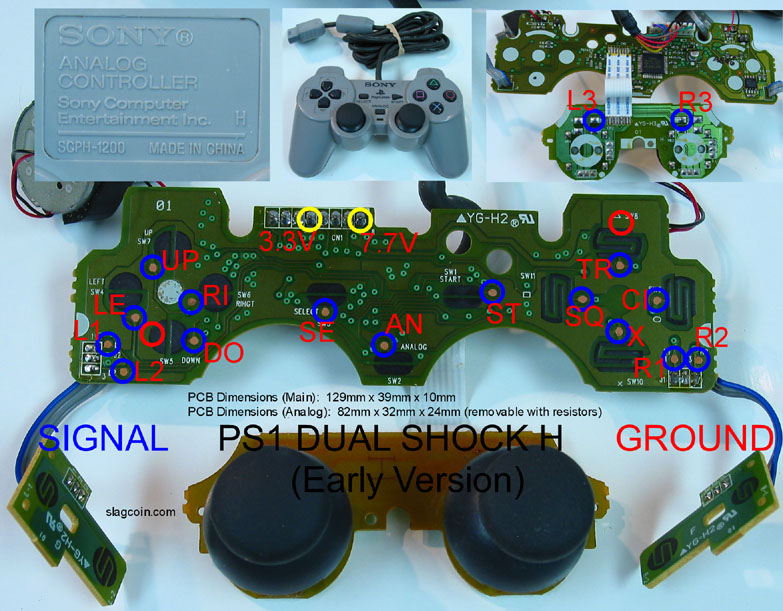
Alright, first time padhacking. Looks like I picked up a PSX Dualshock H.
So, the inevitable questions:
-
The slagcoin diagram shows two grounds. I guess the left one would be for directionals, the right one for buttons? Or is it how ever to my liking?
-
I can cut the wires of the shoulder buttons since those are just contacts right?
-
Analog doesn’t need resistors and I can just take off the rubber?
-
What’s the most reasonable way to mount this into a TE? I know I’ll have to desolder the wire and put it through the storage compartment before re-soldering it back together.
Four questions. Deadly.
-
Same thing, ground is common. You can use either.
-
Yes
-
Yes
-
Hot glue works, but whatever you come up with is fine.
Oh for #3 yes you can take off the rubber parts (and glue them in place if possible) but leave the board connected with the ribbon wire.
Thank you Lucky Day, hopefully those answers took care of everything.
Hello everybody,
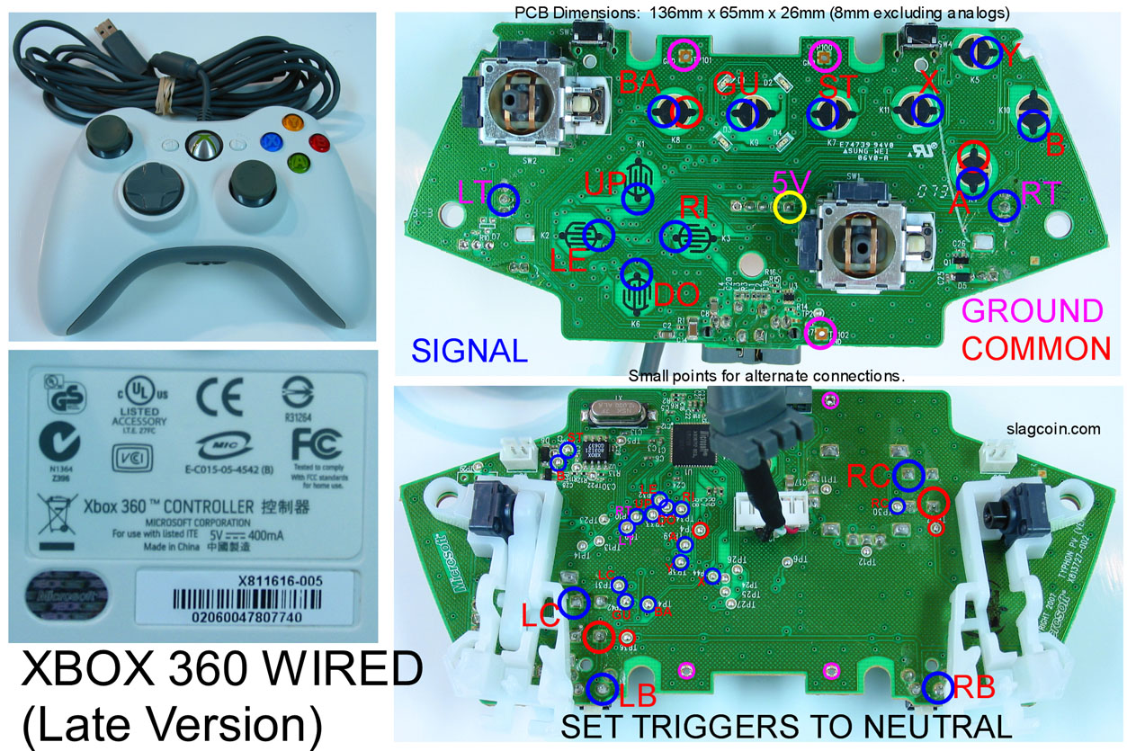
I have an Xbox 360 padhack, It’s a ms wired late version : http://www.slagcoin.com/joystick/pcb_diagrams/360_diagram1.jpg
It works fine until now … Dpad Down is always activated, and no bad soldering, can you please help me to fix this problem ?
Check for exposed wire shorting on the pad. Pics of solder joints might be helpful.
Thanks for your quick reply, so there is no connection between TP4 (CL) and TP35 (DD), tested with a multimeter.
Ok, here’s a question that might be a little less basic and I’m looking at guys like Toodles and Gummowned on this one.
At Season’s Beatings this year I hacked a couple of PS1 pads and wired them straight into the UMK3 arcade machine (ran input lines to the arcade panel itself along with GND, and then rigged controller so buttons would bridge them, long story).
I would like to take this a step further and do this without having to remove the carbon pads and being able to use this with a dual shock pad.
So here are some thoughts and questions that some people might be able to shed light on.
-
Without power running to the PS1 pcb, the carbon pads on the pcb itself and the rubber pads on the buttons won’t conduct electricity and register inputs when pressed as far as I can tell. Is this correct?
-
If I get +5v off the arcade machine, and run that into the 3.3v on either a PS1/PS2 pad (like this) will button presses register on the 18 points like normal?
-
What would be the effects of drawing power from the arcade board and going to two PS1 pads, and would that affect anything (similar to when you have a dual mod setup and plug in both contr
I’m not understanding what you’re trying to describe. Any chance of drawings describing what you’re wanting to do? What all does the finished job have to do?
Ok, so here’s what the original method was, and it’s super ghetto (but worked perfectly in the end, the tourney winner actually used one of the pads).
*the adapters we had for Jamma to ps2 didn’t work on UMK machines. Something to do with Midway machines being wired strange, but I don’t know the full details).
I started with this pad:
I scratched off the carbon over the buttons/dpad to expose smooth copper surfaces (the black material under all of the blue circles)
Then I got some aluminum tape and adhered it to the under side of the buttons themselves (cut it to exact size of the rubber pads under the buttons).
What this did was allow me to hack the pad from different areas of the pcb by getting the traces closer to the center of the pad and reassemble the pads without them being affected in feel.
Then I wired pads and the arcade panel on the 1P and 2P side up with DB15s and hooked them up that way.
What it resulted in was two ps1 pads that when a button was pressed, the aluminum tape would bridge the copper spots I had exposed on the input, trigger it on the arcade panel and have a lag free input.
Needless to say, despite the fact that this worked, it was a total pain in the ass. I’d like to revise the method and make it in a way I can easily hack ps2 pads quicker and add them to the UMK machines (once the machines were fitted with DB15 inputs it would be universal).
So let’s take this PS2 pad for example:
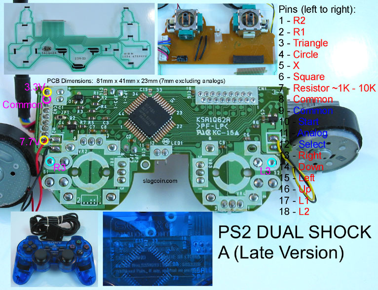
You can easily get the inputs from the 18 pins at the top. However the buttons don’t trigger the inputs without power running through the pad.
I’m wondering whether if you provide 5v to the pad, if you can leave the controller intact and it will send signals out through those 18 pins when you press the buttons.
btw, the reason I’m doing it this way is partly for hobby and to see what’s possible. I understand there are probably better options out there, but I don’t know what sort of adapter will work with an MK machine correctly and without lag.
If this does somehow work, it would also allow me to take people’s pad of choice, wire them with DB15 and have something that works on an arcade machine.
I could also be completely dillusional and maybe this isn’t even remotely possible. But I managed to figure out a way with the PS1 pads, so I’m looking for new ideas to expand upon it.
So you modified PSX pads, ignoring or getting rid of the electronics in it, and wired up the existing buttons and dpad individually one-signal-per-pin to a connector on the cabinet, which was connected to the matching signals on the jamma harness, so the frankenpad could be used instead of regular arcade controls. Sounds like I’m with you so far.
First off, there’s not really a need to connect the power to the frankenpads at all; the idea is for the pad to connect the signal line to ground when the button/direction is smooshed; this is exactly what the original buttons and stick does; No need for power at all. The only thing there to worry about is if the existing electronics on the PSX pad try to interfere. I’m assuming you are ok losing the existing PSX support of the frankenpad. If so, you can remove or desolder the existing electronics from the board, or just use a dremel to cut all traces before they connect to the electronics. You could try to keep the existing PSX support as well, but then you’re effectively dual modding the pad; when connected to the cabinet, there would have to be a +5v power supply coming from the cabinet that connects to the vcc line used in the PSX cable. That’ll keep the electronics powered and keep it from trying to drain power from the signal lines. If you dont care about the PSX support, remove or disable the electronics and you wont have to mess with power at all.
And of course you can just use a pair of FGW Converters and female PSX ends of extension cables to allow any PSX controller to be plugged in and used, without needing any modification to the controller at all. I dont know what problems you had laugh converter, but those work well too. I dont know of any UMK3 specific reasons why either one wouldnt work.
Yup, and with some modification this is exactly what I did, with perfect results. But as I said, time consuming and maybe not worth doing 10 more times.
We’re looking at doing this with a decent amount of setups and making this a universal thing. Laughs converter might work, I didn’t have the time and one available to try it. But the cost on this method is extremely low, lol. I like cheap things (and I like to work and learn as I’m doing it).
Ok, let’s focus on this, because it’s my main question and concern.
A regular PS2 pad works like this. It’s got the copper pads covered by a layer of carbon. The rubber button is also covered in carbon (I’m assuming it’s carbon, if I’m wrong correct me, but I know carbon has this consistency and is conductive).
When you ‘smoosh’ the button on to the two black pads, it joins them and grounds the signal.
However, when you have the ps2 pad unplugged and you take the multimeter and put one end on the signal, and one end on the ground it doesn’t show continuity when you smoosh the button down to join it.
Is it the rest of the electronics in the pad that is preventing this from happening?
I’m almost positive I took the two ends of the multimeter, held them to the actual pads and bridged them with the button and still didn’t get it to ground.
I actually even held both ends of the multimeter to the pad on the button itself, and it’s not conductive by itself at all.
This is the part I’m not certain about, how those little carbon pads work exactly.
If all it takes is giving the pad 5v (which I can do easily) and then those pads work, then I’m in business. It’s going to be extremely easy to wire any pad on the planet to a cab.
But I’m not sure on it.
Yup, don’t care about psx support. I’ll trash the whole thing if needed as long as the feel of the original ps2 pad doesn’t change and it’s responsive.
I’m not familiar with FGW converters, can you link or show what you’re talking about? That sounds like an option.
Laughs converters should work. But they have a plug for a psx pad only. And like I said, buying 10 of them is expensive (but maybe worth it in the end)
If what I’ve got in my head ends up working (especially with an easier method) I could theoretically use DB15s and add 360, Saturn, PSX, SNES and all sorts of pads to any arcade machine sometime down the road.
UMK guys are a pain in the ass, lol. They use a ton of different controllers.
-
All correct. I dont know if its actually carbon, but you definitely have the right idea on how it works.
-
I can assure you it does make a connection, but the connection may be different from what you were testing for. The connection made isn’t as clean as a direct metal-to-metal connection like microswitches make; there is a good amount of resistance still present. Even cooler, the harder you press, the less the resistance, which is how PS2 and Xbox pads can tell when a button is lightly pressed versus heavily pressed (think DOA:XBV or Metal Gear Solid). But there will always be a noticeable amount of resistance, and if you were testing with a meter, it could have been confused. If there is resistance, a ‘continuity’ test mode will likely not beep. If you were testing using the ‘resistance’ setting, and the setting was too low (i.e. using the 20 ohm range), it would apear to be an open circuit because the resistance was greater than the test range. Set the meter to test resistance in the 2k ohm and 20k ohm range and it should be obvious; if not, keep going to higher ranges until you see it, but I think a hard smooshed button would normally be like 100-300 ohm, but Im sure it would be different for each pad.
-
You have a choice; either connect power to the electronics on the pad, or remove/disable the electronics on the pad.
-
Bottom of first post of Cthulhu thread, they’re listed in the stuff I sell plus a link to the welcome doc pdf. It should tell you everything you might want to know about it.
-
The idea is sound, sure, but you will have a more difficult time trying to do this on pads that aren’t setup for common ground and trying to use any analog inputs like triggers.
All good info, thanks. I did know about the resistance on the buttons and how that worked, but not all the specifics of how the power affected them. When I didn’t see continuity between the points when they were joined I figured I had no option.
I will do some tests like you said to play around with how it works.
So essentially you’re saying that if the pad here i supplied 5v, and I wired it up according to that diagram to the arcade control panel, button presses should activate those switches?
When you say ‘remove the electronics’ what is the extent of what I have to remove? Can I just cut the cable off, slice out around that chip in the middle and be done with it? Or will I have to go trace by trace and make sure each one is removed from all resistors, and anything else that could possibly be on the board.
This seems like the more time consuming method of what I’ve got so far, so I likely won’t be doing it, but just wondering.
Those look amazing, and might be exactly what I need for it. Can’t believe I didn’t know about it. Sharing the 5v from the arcade machine with this should cause no issues right (same as a dual mod), and these are definitely lag free from the looks of it.
My thought is if I get a ps2 pad, saturn pad, 360 fight pad, and SNES pad that’s enough. And they’re all easy to do with a few methods apparently.
If someone wants a non-common pad to work I’ll show them where to stick it, lol.