I have a question about this PCB:
How would I get to either of the ground points?
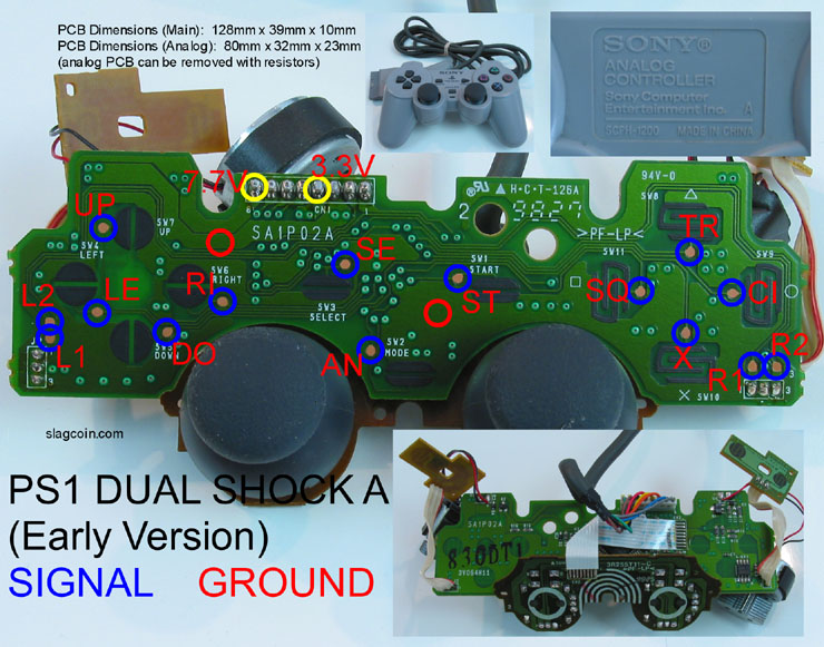
I have a question about this PCB:
How would I get to either of the ground points?
if the ground point is UNDER the green coating, you have to scrape it off with a hobby knife or something like that. for this though, you can just use the middle solder point between either of the shoulder buttons (shoulder button solder points are marked by 1 & 3 where the cable comes in at the back)
Oh my god, I love you so much right now.
This trigger hack is about the same thing as the one for the Wii classic controller, right?
If so then YEAH! I can finally start for real now!
Anything opposite a blue circle is Ground.
There are at least eleven more easy spots for Ground.
Are there tutorials or guides on about Moding or hacking Mad Catz fight pads in this thread? theres over 100 pages and i just dread on the fact of searching through everyone of them, anyone info would be appreciated greatly =]
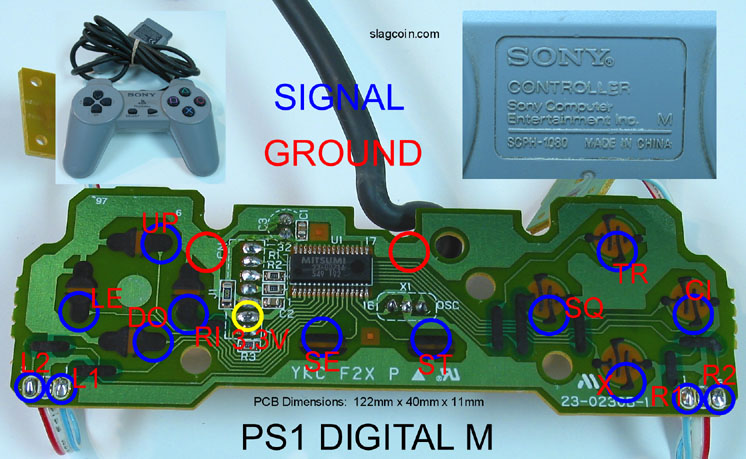
hi, maybe someone knows. i’ve hacked 2 PSX controller PCB’s just like this one: http://www.slagcoin.com/joystick/pcb_diagrams/ps1_diagram4.jpg . Both have worked well for a while. one worked great until I made the installation permanent inside my cabinet, the second failed after I hotglued the connections. the failure symptoms are identical, its like the up button got permanently grounded on, on any menu it just scrolls up and won’t respond to any other input. i know my installation is sound, i’ve got a Dreamcast PCB hacked and installed and working, a PC controller PCB hacked and working, just not the damned PSX! Any ideas on what to troubleshoot, i’m buying a nubytech street fighter ps2 now, they look simple.
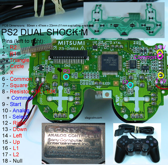
I have three ps2 controllers. one is an H and 2 are A’s. I have searched high and low, and i have not found a tutorial for hacking either type. It is really confusing because they have the strange flexible pcb where the buttons are, rather than solderable contacts. are these unhackable? someone please lead me in the right direction.
They are hackable, what you most likely will be doing is soldering wires directly to the pins under the harness that the ribbon face plugs into. You can refer to slagcoin’s diagrams if they match, or you can find them yourself with a multimeter.
^the pcb’s you are referring to are the “Spiffyshoes solderless hack” variety. these are my favorite for PS-DS1’s because of how easy they are to “Padhack”. link for the tutorial:
thanks. ill give that a try
I didn’t read the whole thread but does anyone have a picture/guide for an the original xbox “duke” controller?
Hello im having problems with a Mseries PS2 dualshock pad with the film connecters it appears on the pc completely ligthup on allmost every button does anyone know a solution ?
You Daisy-chained the Signal instead of Ground?
Here is the pad I used to dual-mod my stick for Wii support (dunno if i should make a new thread about it):
Nyko Wing Wired Classic Controller

I don’t know if it’s the ideal controller to hack (over say, a 1st party CC or a GCN controller) but I got it for $10 CAD at Walmart and being a CC its pseudo-wireless.
What you need
Anyways after you unscrew everything (don’t cut off the analog stick PCB) you will wind up with this:


One thing to note is the wire catch is glued to the controller, so you may have to use a little bit of force to get it off.
First thing you want to do is use a gluegun and glue the wipers to their neutral position, which is with the movement knob pointing directly up. You can also take off the extra plastic, and you will have a half-circle. Neutral is also the the flat part facing directly up.
Here is a labeled PCB diagram:

As you can see there is L and R have both an analog signal (the wiper) and a digital signal (where you see the wires sticking out of the PCB). Some games will only register the digital signal as an input (eg. The Wii menu) while others will only register the analog signal as an input (eg. Tatsunoko vs Capcom). I’m pretty sure most here would only be dual hacking for TvC, so I will explain how to get both working.

Basically what I did was use a PNP transistor (2N3906, I had a box of em, they are** very** cheap), link the collector to VDD, the base to the digital signal (through a 10KOhm resistor), and the Emitter to the analog signal.
I can’t take full credit for this method, I found this method in a thread here detailing how to get both analog and digital triggers working for gamecube, and just (correctly) assumed the same thing works for the classic controller.
Look VERY closely at the PCB and the orientation of the transistor. It’s easy to overlook this and put the transistor on backwards.** KNOW WHICH LEAD IS COLLECTOR, EMITTER AND BASE!**
Also, the Analog signal and +VDD are right next to each other, don’t make them touch. Here is the pic for the left side (forgot to take a pic for the right side sorry, just look at the original PCB diagram above)


You can test your progress by using the Wii menu and TvC. If you can change channel pages with L and R and they work in TvC as well, you did it correctly.
Here is where the gluegun comes in handy. If you glue every connection (don’t worry about being neat, slab it all over the place) you get additional protection against shorts. The glue doubles as an insulator to protect wires from shorting, and extra support to prevent the wires from moving and potentially rip off the contacts.
That’s pretty much the only major hurdle, if you are dual modding make sure to link your ground wire to the ground of the first PCB, and the +5V of the first PCB to VDD (labeled in orange in the original PCB diagram)
Note
I think there is something with this controller that makes it not work in TvC unless you plug it in after the game starts. Maybe it’s just me, it happened before i even took the controller apart. If it doesn’t seem responsive just plug it out and in and see if that helps.
Nice guide, threi! Glad my mod helped someone out! :tup:
-ud
Toodles
This may not be the perfect thread to ask in, but I’ll ask any way. I built a joystick a few months ago and used a wireless xbox pcb from HarumaN (who did an excellent job)
My set up looks like this.

I have the plug and play wireless battery set up that charges via usb. My question is can I add a toodles board to the joystick to add xbox/ps3 functionality? It seems as long as the xbox controller was turned off I could just ‘tap on’ to the wires to each button and have another separate usb for the toodles board. I don’t know a whole lot about wiring, but it seems it should work.
Thanks in advance for any info.
I believe that wireless controller is common line, not common ground which is needed for a chimp/mc cthulhu dual mod. If it can be done, this would be your go to guy.
Hi everyone!!!
Did anyone have done a Mseries PS2 pad hack ? i would like to know where to solder the resistor ? Can anyone please help me…
Hi everyone!!!
Did anyone have done a Mseries PS2 pad hack ? i would like to know where to solder the resistor ? Can anyone please help me…
i allready removed the vibrator motors and the pad apears completely light up on the pc. I want to use it on the pc and on the PS2.