New problem - the guide circuit no longer functions. I’ve soldered the main to S32 (left side) which is electrically continuous with S12. Before I put the board into the stick, grounding this main activated the guide GUI in windows. After putting the board into the stick, the circuit no longer functions, even though all connections test good. Grounding the main doesn’t activate the guide GUI (nor do anything else). The guide button also doesn’t function on a 360.
Hey guys, i was wondering if anyone can help point out where to solder the resistors on a custom PCB i have? I’ve attached 3 images and i’ve been pulling my hair trying trying to work out what resistors to attach and where.
Back again, with dual mod issue. I have been having problems getting the 360 pad (madcatz gamestop) to work with IMP. For some reason, I just cant get the 360 pad to boot up. I have both pads buttons, directions, ground and 5v connected. The cthulhu portion works correctly on my stick and the T.E edition pcb worked fine in the second stick I tried (last night). I just am not having any luck with the 360. I have the D lines hooked up to their respective places (on both sticks ps3 is the main in the 1st d line set on IMP) with 360 as the secondary. The ground and 5v are also hooked up correctly (otherwise I imagine that even the ps3 portion wouldn’t work correctly).
I’ve been trying to think what could be wrong with my wiring, maybe its an issue with the guides being hooked together and a line going to the imp? I currently have, on the TE pcb, select hooked up to guide (because whatever is hooked up to guide is the button held on power up to switch pcbs, correct) but still nothing. I was also tinkering with the ls, dp, rs switch just to see if it made a difference and I didn’t have any luck with that either. Any ideas or help would be great.
I tried again tonight. No luck with select, I wanted to make sure that the 360 pad even worked so I swapped the 1st d slots on the pcb and lol, sure enough 360 pad is working. Am I just being dumb and missing something small? Ideas? Thanks again.
EDIT NO JUTSU: So, the problem was bugging alot. I didn’t think it would matter but, instead of having the imp wired directly to the ps3 pcb, I decided to try it with the wiring to the button. And for some reason it worked. Why? I have no clue. It doens’t make sense to me because I imagine that the signal is EXACTLY the same type of signal it WOULD have received otherwise except farther along “down the line”. Well, whatever the case, I got it to work.
I put this in the general/noob thread but I figured I’d try here as well. While taking apart a Madcatz controller, the trigger contacts fell off (well, high didn’t). I have done these before and I only need the wiper contact (the middle one) on the left side. Do these trace to anywhere or is this now a 6 button pad?
can you resolder over a solder if you cut the wires but theres like a piece of the wire left? Will it still work.
The wire is too small of a piece to cut.
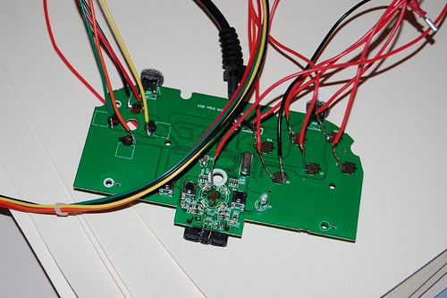
Got one of these in the mail today, took it apart and low and behold, it is common ground! I don’t know if it’ll work on ps3 but I’ll test it when I can. The pads for where you solder are teeny tiny but doable.
Question - I have a LED balltop I got from Luigi that just has 1 led in it with a ground wire and the wire with the resistor. I want to light it with an external battery source instead of off the pad, and perhaps add a on/off switch. What all do I need to get this working? I assume a battery pack case can be obtained from Radio shack, but how much power do I really need for one led?
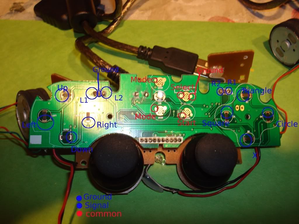
The alienware dual mode controller for ps2/windows isn’t 100 common ground, but for all the stuff that matters. Might have the right 1/right 2 and left 1/left 2 mixed up since this was based on button numbers in windows.
does anyone have a diagram of the horipad ex Turbo (blue) for the xbox360? been trying to find diagram for a while now couldnt find any. Any help would be appreciated.
i mean… i just need UP,DOWN,LEFT,RIGHT SQUARE,CIRCLE,CROSS,TRIANGLE,START,SELECT (ps2) or U,D,L,R,A,B,X,Y,START (dc) … which one is the easiest pad to hack? i found on the first page the pic of the DC one but i don’t understand where the ground wire/s whould be solded on…any help?
