4.7k resistors are fine, any wattage is fine. Take one resistor, connect one leg to black. Take the second resistor, connect to white. Connect the free legs of the two resistors together, and connect that middle point to red, blue, yellow and green. A multimeter should show orange and white are connected, if Im reading the board right.
White?
I have it labeled with
Black
Pink
Orange
Purple
Yellow
Green
Blue
Red.
Maybe I accidentally used Magic Magenta and the pink is coming through transparent?
I’m seeing two white dots on legs in the lower right of that picture you posted.
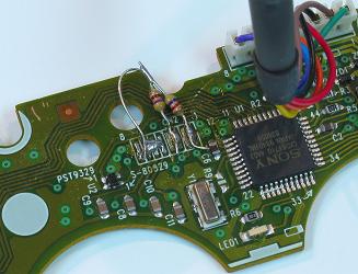
Those are where I made a mistake tracing from the ribbon cable. I’m trying to completely remove the analog board like in this picture http://www.slagcoin.com/joystick/pcb_wiring/h_after.jpg .
If you know the points I’m talking about, why are we still talking about this? If orange is connected to the ‘white’ points, then you have all of the colors you need, using only two resistors, with the description I already gave. If there’s some crucial piece of information you’re missing that I’m not seeing, please be very specific about what it is.
Sorry about all the confusion. I’m guessing you are trying to say that if the white is connected to orange I should just solder to the orange than? I’m guessing they are connected through the analog stick somehow? I fixed my diagram to be more clear if it helps. Sorry again 

If the cable has 8 wires it means there are 8 “things” on the PCB, hence you shouldn’t use more than 8 colors or it becomes inconsistent and confusing. And remember when I said that I was going to do the edit, not you?
Thanks very much. This is actually how I ended up wiring it up. I was just trying to label since I had no removed the ribbon cable and it was blocking the traces leading to the right side.
Thanks both to you and Toodles and sorry again for being mildly retarded and making a mess of the last page of this thread.
Anyone have a diagram of the Wii classic controller by any chance? I only saw a diagram of the Intec model but that controller is not sold in my area. I’m also aware of the resistor method for L/R but I’m not gonna need it.
A few dumb questions that are probably already answered but buried within 150 pages:
I’m going to try to make a stick out of an official wireless 360 pad, mostly because I have an extra one lying around.
The image in the OP specifies wired, does that mean the wireless ones have different solder points?
How do you go about wiring the triggers/bumpers? I just want RB and RT.
Do you need to cut a hole in the back of the box for the wireless signal or is it fine enclosed?
I don’t believe any controllers use IR anymore so enclosed in the box should be fine.
Could someone provide a detailed explanation as to how you go about using a multimeter to check for shorts? I’ve found several references using the search function, but none that really break down what numbers your looking for or all of the points you should check for possible short circuits.
Also, one of my main concerns–especially considering this is my first experience with soldering–is that while everything may check out fine now, somewhere down the line one of my soldering points may become disconnected, cause a short and seriously damage my Xbox 360. Is there any way at all to include some component into the hacked pads that would protect the console should some point fail and a short become an issue?
Thanks in advance for any help anyone can provide on these issues.
nikkyo
Does anyone know of an alternative solder point for the Madcatz SF4 Fightpad guide button for the 360? I’ve torn my traces off the PCB, and don’t really know what to do to fix it.
A gentleman has told me that s12 above the guide trace is an alternative soldering point. Also, it seems that on the back, c32 on the left side might be yet another. Sucks that the guide button doesn’t show under windows.
it does if you have the drivers installed for the wireless receiver for the pc.
the guide button will show, but if you don’t have the microsoft controller drivers installed, simply go into your control panel under game controllers and look for the button press to show up on that screen instead.
I’ve got the drivers installed, so when i press the home button a small GUI pops up with the status of my controller, and which player number it is (looks like the green ring on the controller).
nikkyo, technically? yes… you could put a low(er) current fuse in on your power line, something like 1A would even suffice, since USB should only source half that at most consistently.
As for checking for shorts, just google some procedures, you’ll get better information that way.
I only have whatever drivers are automatically installed with Vista, unfortunately.
“Guide” doesn’t seem to show under Control Panel -> Game Controllers -> Advanced, while every other button does, and no GUI pops up when I connect a ground to S12.
Yeah, you’ll have to search for the game controller drivers put out by microsoft.
Thanks guys; this is everything I need!