Quick help guys. I have a ds pad im hacking that there is no diagram of. I hacked it already with no issues. But now i need to find the 3v so i can use it in a dual mod. I bought a cheap little 15 range multimeter from radio shack. What settings do i need to put it on to get the reading im looking for? When i find the right pin will it read 3v solid or will it vary around the 3v range?
thanks
You want to put it into DC Voltage mode 20V or so mode would be good. (The top-left section of this image where there’s a V and a solid line over a dotted line. The 20V max listing is what you want from this meter. Yours may have different settings.)
Dreamcast actually uses a 5V connection so you should read something from 4.5-5V (or so) but it should stay steady at that voltage without (a lot of) fluctuation.
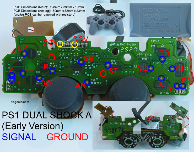
Thanks, on mine its DCV mode and i set it at 20v. Its a playstation dual shock pcb im doing btw.
These were my findings.
8 pins
colors- black/purple/red/green/brown/orange/blue/yellow
readings- ground/0/3.4v/3.0v/3.0v/3.3v/3.4v/3.3v
So which is the one im supposed to tap into for my dual mod? I measured these while the pcb was plugged into my ps2. Originally i was trying to read them off my computer but it was giving me fluctuation, i guess due to the converter.
use the continuity mode to figure out which pin is connected to the power pin on the plug. Pin 5 (its the pin in the middle) is the Vcc line. Find out where it connects to on the pcb.
or its probably just the red wire.
Looking at the pcb looks like pin 5 connects to pin 4
edit-btw, i just gave you the feedback i promised. forgot all about it.
are you trying to say pin 5 on the plug connects to pin 4 on the board?
or pin 5 on the board connects to pin 4 on the board?
pin 5 connects to pin 4 on the board

nope, in that picture, the traces for pin 4 and 5 are going to 2 separate via.
unless you’re talking about the pin5 on the ps plug.
Anyone know if the Alienware Space pads for PC/PS2 are common ground. Also, is it compatible with a PS3?
http://microcenter.com/single_product_results.phtml?product_id=0316260
Thanks
Has anyone, including the original poster, found out which pin to solder to for 3.5V? I would also like to do a dual mod with this strange ps1 pcb (and the Madcatz arcade stick pcb).
Cheers.
bit of an odd question. So I’m re-purposing a Tekken 5 stick, and this thing was beat to hell.
Now, I’ve got the PCB and part of the wire that has the plastic connector that goes to the pcb (pretty much all of the cord that was inside the controller, it got cut at the the controller before i got my hands on it). The PCB is in good condition, I’d like to use it, but my question is, what’s the easiest way to figure out which of the 8 cables from whatever controller I ransack goes to whichever of the 8 wires I already have?
the only idea I have is to add quick disconnects to all of them and try out every combination, but that sounds like it’d take quite some time.
Hey guys im padhacking a ps3 sixaxis at the moment and ran into a problem. I soldered all the pins already and added 8.2 resistors on 7-8 and 13-14. When tested it only the Ground+PS home button work… Everything else doesnt. I’ve resoldered everything again and same problem. All I can do is turn the controller on but the other points wont work. Does anyone have an idea why this might be happening?
I have a feeling the resistor is the problem on this one. Either the way i connected them or the value i bought.
I made a diagram on how i did it. Is this correct? or im i doing something wrong. Please help
http://i.imagehost.org/0574/untitled_8.jpg
Is 8.0k the same as 8.0ohms? sorry for the noob question
quick question, why do you have a resistor between those pins? is it meant to be a pull up/pull down?
If that’s the case then YES, 8.0Ohms is very different from 8.0k ohms
Really though I’m curious, because if you’re hacking a pad… it already has pull ups/pull downs on it’s board by design for it’s original use.
edit:
I see… you’re following this: http://www.slagcoin.com/joystick/pcb_diagrams/ps3_diagram2.jpg
Yeah, you should change those out for higher value resistors.
just bought a higher value 8.2k resistor and did the setup again but had the same result.
Can anyone help out? Is my sixaxis busted?
Ok I just searched this thread for about two hours and came up empty. Can anyone tell me where to solder the resistors on this pad http://www.slagcoin.com/joystick/pcb_diagrams/ps1_diagram8.jpg ? I’m trying to completely remove the analog board.
Post a hires pic of the solder side of the analog board (after desoldering the flex cable) and I’ll edit it with the resistor info.

Sorry didn’t want to desolder until i got the resistors but i followed the traces. Are 1/4 watt or 1/2 watt 4.7k resistors ok?
doesnt slagcoin have a long article on how to do it with that exact pcb?
My PCB is version A. The one on slagcoin is version H. The ribbon cable is on the opposite side of the chip so I just wanted to check with someone who might know offhand.