First time padhacking but this is the only part i have questions:
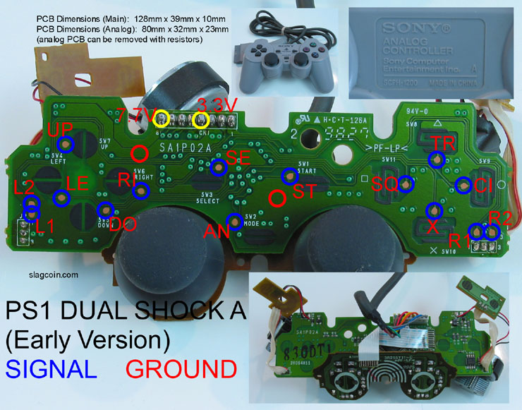
So for the 2 grounds (red circle) i just solder a wire to the green part? No metal contacts or anything right? Then from there I can use one ground for the joystick and the other ground for the buttons.
As for the L1 and L2, i can see the circle, but which line in those circles are for which signal? On some other pcb diagrams i see it scratched out to expose the metal, but not this particular pcb.
And for the 3.3V, i don’t need to do anything to it if it’s just for a single pcb stick correct?
This is not for a dual modded stick, just something so I can use on the Ps2. Sorry for the n00b questions, but it’s been bugging me lol.
And I just somehow managed to pull the exact problem as this guy :(… If I never had any intention of using a trigger button at all, is this going to be a problem for me? He apparently wanted to use it but, I really don’t. I just want to make sure that I don’t take the time to wire up this pad and it shorts because signals from the triggers aren’t available or whatever.
Best Buy is selling Madcatz Fightpads for $23 on clearance. So if you’re using the 4716 because it’s cheaper, now’s your chance to nab something with a wicked easy PCB to solder and NO TRIGGERS/ANALOGS TO REMOVE.
How I found this one? I somehow managed to fuck up my 4716 pad…dunno how either. I plugged it into my PC so I could take measurements on the triggers and analogs in their neutral state (so I could get the correct resistors to put into place). I opened up the control panel and my computer freezes. So I shut it down (improperly…it wasn’t responding) and on boot up I plugged in the controller again…and nothing, it never comes alive again. I check the voltage and it’s got 5v on all the lines (including D- and D+, which I remember toodles saying is BAD).
I figure I shocked something on accident because I never grounded myself before touching the PCB upon plugging it back in…or something was somehow shorted, but I couldn’t find anything with my meter. So I packed it back up and went to exchange it, and found the fightpad on clearance . A little shady, but I really didn’t feel like tracking that issue down.
I’ve cleaned and soldered all my points to my joystick and am working on connecting said points do the board. i have my ground wire attached already so that as i solder it up i can see where th problem is… so the problem is that my buttons are activating the moment the wire from my micro switch hits the board and not responding when i actually press the button. is there a way to break the connection? im working on a dc original and used the points in this diagram.
Would 6 LED’s and their appropriate resistors (right now in 3 parallel lines with 100 ohm resistors on each line) be too much to run off the USB VCC of the Madcatz 4716 pad? Right now they are being powered by an 4 external AA batteries + a switch but it would be cool if they could come on when i plug in the stick.
So if you can actually draw 500mA I think you’re ok, because 6 LED’s with 100Ohm resistors should give you a max draw of 300mA (+/- some because of tolerance), allowing your other component the leftover draw. Again, I’d ask someone who’s done LED mods though to be sure.
Well I know that the led’s would draw 60mA (since it draws 20mA and its in 3 parallel lines) so that should be enough. My worry however is if there is stuff on the pad that is drawing max current, where even a little more will cause some sort of catastrophic failure.
Oh, i see what you mean. I thought you meant you currently have 3 LEDs but want 6, my bad… I also forgot to take into account the forward voltage (you have 2 leds in series per branch, correct?), I hate when I do that
Hmm, well if you have a total draw of 60mA that leaves a lot for the pad to draw on it’s own, and if the wiki is correct and it’s allowed 500mA I think you’ll be just fine, there’s no way a single pad will draw that much.
Don’t most people who do LED mods run it from the USB?
What you’ve done is correct in theory but executed terribly.
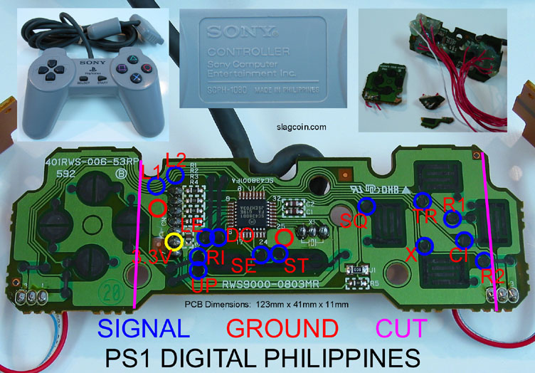
You should desolder that resistor+wire and clean up the PCB with some solvent to get rid of solder debris and flux. Instead of using the via on the other side of the board you can use the spot marked B in the pic below, which is much easier to solder to. If the via A is burned/unusable, you’ll have to use the via C. To solder to vias you have to gently scrape off (with a jeweller flathead screwdriver and a magnifier) the green coating that surrounds them until you get to the copper underneath. Then you tin the area with very little solder (the amount you’re using now is just wrong and it looks like a cold joint) and finally you solder the resistor to it. To sum it up: solder the resistor from A to B or from C to B.
 . A little shady, but I really didn’t feel like tracking that issue down.