Can anyone tell me how to pad hack the saturn mad catz pad? This is a cheap saturn pad, as sold by rob webb on consolegoods.co.uk, not the new sf4 pads.
I’m intending to add it to my TE so i can play saturn games, but having never done a pad hack before was hopin to find a diagram.
I’ve done a search but it just seems to (unsurprisingly) just bring up the mad catz sf4 pads.
Any help from you gods of technology much appreciated!
Heres a photo of the PCB. The arrows are pointin to what look like places for buttons (maybe turbo buttons?), yet on the pad there isn’t anythin there. Any help would be great!
Well, first, that looks like a simple common ground pad and on all the non-directional buttons it looks like the circular pad is signal and the other part is ground. For the directionals on UDLR the left, left, top and bottom pads seem to be ground. All this can be verified with a multimeter.
I would assume that Saturn has a known pinout and runs at 5v so with a meter you should be able to determine which trace is supposed to be +5v. Off the top of my head I would assume it’s the double-pin second and third from the right where the cable connects to the board (from this view) solely based upon the fact that I think the one to the right of it is ground, though it’s entirely possible that it’s common +5v and that double-pin is ground. Unlikely though. Basically, you need a device of some sort to determine which of those pins are +5v.
As for those extraneous buttons – do you know of any similar pads by the same company that has those three buttons because it’s possible they’re still functional.
Oh, for reference, that crosshair in the bottom right of the PCB looks like a good point to take up ground from if you want to get a single point separate from the buttons.
The wire should work… But to anybody, please correct me if I’m wrong. I actually just used the wire in a Cat5 cable so if you have those cables just sitting around then that’s a good option… Those little wires inside the cable are the perfect size but make sure its the solid kind. I also Just recently modded my PS1 DS A-series (late Version)
im trying to put in a new cord
but there are seriously 4 pins where 3 cord wires (a white/green/coatless) are just soldered together
hard to tell in this pic but info would help
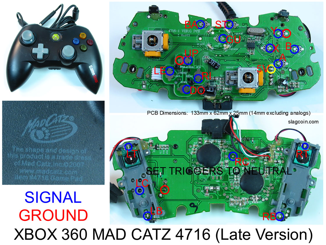
hey guys was i had a few questions and was hoping someone here could help. so the pad i have is a madcact 4716 ver-f 2007, well at least i think that what it is. i have included the a shot of it. basically before i go about trying to pad hack this thing i wanted to ask the the pro’s.
i’m assuming this thing is common ground, this is based on the pcb section off of http://slagcoin.com/joystick/pcb_diagrams/360_diagram3.jpg i know it isn’t my exact pcb, but i’m assuming it’s close enough. can anyone tell me otherwise?
do these triggers need to be inverted? this i assume is a yes also. but figure i asked anyway. although i’m not doing it yet it be nice to know for when i work up the balls for it.
in the slagcoin link what is the 5v yellow circle for? i was planing on wiring my controller like this, is this wrong? should i be doing something with the 5v point?
would i just be better off returning this back to gamestop for a 08/09 version?i figure this way i can just follow the tut here
lastly other than here and slagcion is there any place else i can go for pcb wiring diagrams. doing a search in the pad hacking thread as well as google just brings up 08/09 diagrams or just way too much to filter through. whats nice about slagcoin is it list the pcbs
thanks guys. unfortunately i’m a complete noob to pad hacking but i’m not to soldering and doing mods. looking at all the tuts here and as well as the stuff on slagcoin it looks like stuff i can handle. lol hopefully i won’t be eating those words.
slagcoin is the best place, every once in a while a new one will pop up on SRK. There are a few he could update on slagcoin, but for the most part it’s a good resource.

