does anyone know if the red xbox controllers with play and charge kits are for sure late model common versions?
i have a madcatz xbox 360 sf4 fight pad i soldered it into my mass stick,the board is alone i did not solder the xbox button now once in a while the xbox button presses on its own sometimes random presses sometime it hold for the console off screen any help theres no solder on anyother part of the stick maybe i did somethign wrong i used the left directional for common ground ; ` ( oh yeah perfect 360 and the 5 volt is direct to the first joint on the board from the cable.
Hey guys. I’m going to start my first dual mod. I’m using a solderless A-series that I want to put in my TE stick to dual mod it (i would just do a Cthulu but I’ve got lots of A-series sitting around that I want to use since I have no use for them). I’m using Spiffyshoes’ guide for the wiring order on my A-series. I only have one real question though, do I need to connect anything to the 360 TE stick in order to dual mod it other than the Ground and Buttons+Dpad? Do I need to worry about the 5v?
If I have to connect the 5volt then can I get an explanation on what I need to do? My first problem is that I don’t know where the power is on the PS2 controller, spiffy’s guide doesn’t show it.
Yes, you need to connect the ground and VCC between both pcbs no matter what if you plan on dual modding it.
The power on the PS2 controllers (the majority of the time) comes off the strip of points that runs down the side of the controller. The one you want for a dual mod is usually on the end of that strip. In this case you want the 3.3v

Good. Seems easy enough. Now my only minor annoyance is that I have to drill a bigger hole so 2 cords can come out of the box… I don’t have any drills so I might have to do it some ghetto way.
I have another question haha. I’m planning on building a 360/ps3 stick very soon in the future. For the 360 portion, will it be okay if I use a PCB for a wireless 360 controller and just plug it in through the USB with an imp?
No, I don’t think the wireless 360 controller has any of the points needed to connect the pcb to the IMP.
Sorry, noob here. What’s the Flux for???
You add it with a capacitor to make a flux capacitor and thus enable viable means of time traveling!
or for the real answer check wiki
quick but probably dumb q - the 10k resistors you guys have been using for the triggers/analog sticks for 360 pads… any particular wattage? I’ve looked around and noticed the wattage on that ohm resistor type can vary between 1/8-1 watt. I’m assuming the 1/8 will be perfectly fine, but I’m not sure.
1/8 should be fine but most people go with 1/4 watt – they’re somewhat more common.
One better question considering the prior, had I not been retarded and searched again including the word “watt”, might have found the answer and not wasted a post:
Currently yanking triggers/analogs off a madcatz gamestick. My soldering skills are fair, but my desoldering skills evidently need a lot of work 'cause I’m having issues with this. I can suck up a fair amount, but on just about every pin, there’s just enough solder left to not let go of the pin, but I can’t seem to reheat well enough to remove. Also, this solder they used is odd considering that my two heat iron is too cold at 20W, too hot at 40, so I’m also constantly bouncing between the two to keep it in the middle. I was thinking that adding more solder and attempting to desolder again might be a better solution, but I don’t know how possible this would be when it comes to mixing solders, as the solder I have heats up just fine at 20W. Any tips on fixing my failure?
If you’re having trouble desoldering at a temperature where you can solder then try adding either flux or a bit of fresh solder to the old solder. Also, what tools are you using to desolder?
Just a solder sucker? Just braid? Solder sucker and braid?
When stuck I sometimes clip off the component so just the leads are left, attach locking pliers to the lead to add some gravity to the lead then just melt the solder and let the lead drop out of the board.
fellow shoryuken’s
hope u can help me, i have this pcb.
http://slagcoin.com/joystick/pcb_dia...2_diagram2.jpg
this my 1st ps2 pcb to mod, and i realy noob.
can someone do a tut for me on how to wire it up? and which wires go where.
and the resistors on where to put. if its needed.
i need only the following buttons:
> up, down, left, down
> x, square, triangle, o
> start
hope u can help me.
Just solder sucker.
At this point all the components are removed (the analog sticks were an absolute bitch, I must say. Wonder if that’s a universal PCB issue or just this one). A few points remain that still have a chunk of leftover lead and solder holding it there. In some cases, the pin is melted into the solder and the leftover solder that exists is thinner than the PCB in amount. I’ve had no success in melting more of my solder into the mix, which I’m to believe has something to do with the fact that the solder on the board has a higher melting point than mine. I can suck away what I put on, but it does nothing to remove the leftover solder that I still cannot remove.
I feel I should snapshot it and present to you what I’m calling a total mess in some places in order to have a better understanding of what I’m working with at this point. 
Is that a Pelican or a Madcatz?
Gamestop (Model #BB-070).
Hello everyone. I know what I’m going to ask was probably discussed already but I need help wiring a PS1 DualShock Series A (Late Version)
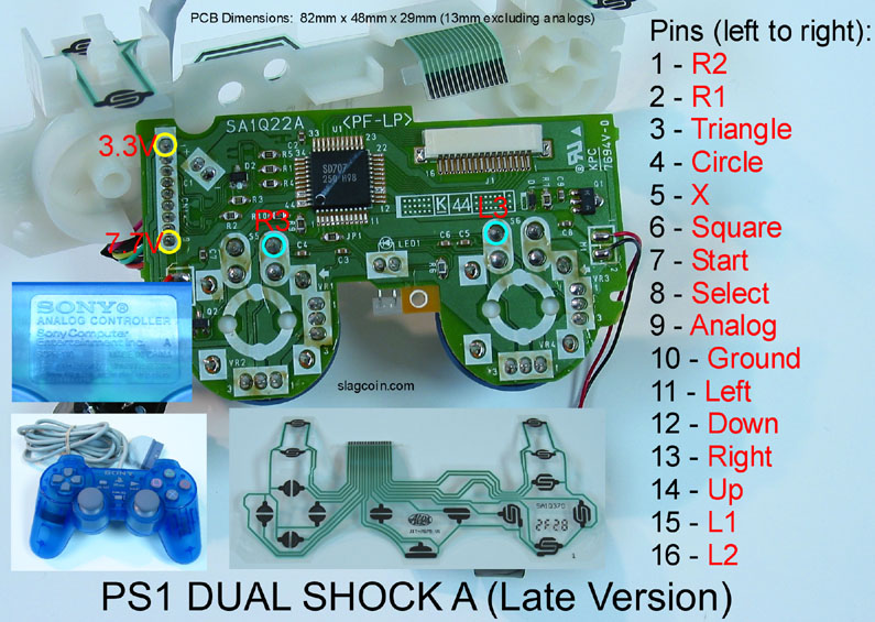
Its solderless so I connected the wires in the Terminal according to the order from 1-16. I connected the wires to the buttons and joystick. I daisy chained the Ground wire but the “START” button is the only button that activates. I connected the wire in the START Button Terminal to every microswitch on the buttons and joystick. All the microswitches that was connected to the START Button wire activated. I’m scratching my head trying to figure it out. If anyone can help me or link me to another thread. I greatly appreciate it!!!
Nvm…I figured it out… =)