Yessir.
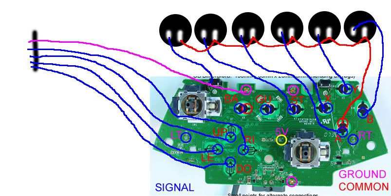
besides model#024 wireless xbox360 controllers being common ground what else model numbers are common? there are a lot out there …
OK, so I cut the ground traces on the LS-32 and soldered directly to each ground per direction. I’m still using the harness for the directional signals from the pad.
In the 360 menu now I can move any direction and its correct…but in any game (MVC2, Dishwasher Samurai) the joystick is getting a constant down signal…meaning, is the anlog stick stuck in a down position?
So…one of my resistors isn’t doing its job where I removed the analog sticks?
:chainsaw:
Whats the color code on those resistors? Is it Green, Brown, Red (5.1k) or Green, Brown, Orange (51k) ? Try using a 10k instead (Brown, Black, Orange). Also, the pic you showed is the right analog stick spot, is the left one set up the same as well?
I used 10K 1/2 watt resistors (the ones in that pic are just an example from RDC’s post from xbox-scene, he even says they are the wrong type but the placement hopefully is right) and yeah, I did both sticks so 8 total (+2 for the triggers).
…I’m guessing I just missed a point somewhere.
edit
You know, I cut those traces on the LS-32-01 with a razor…guess its possible I didn’t get all the way through.
Perhaps I should use a dremel? I mean…the cuts I made look like I interrupted the path.
I even eliminated the harness completely.
Ok…if anyone can help, please contact me ASAP!!
So, i have this PS3 street fighter 4 te stick that i need to dual mod. I already make custom sticks but this is my first dual mod. I need to know how i would connect my xbox pcd that i gutted from a wireless controller to the existing pcb in the stick. If anyone has any info or can direct me to a place that does i would greatly appreciate it.
…thanx
Hey Guys,
see the common wire going from button to button
HOW do i do that ?
run wire to first button… crimp it and a short run of wire to the disconnect, rinse, repeat…
sorry pretty bad on all terminology

see the metal thing where brown wire is going ! do i open that, can that fit 2 wires?
Yeah…when I removed the analog sticks I must have fucked something up. Oh well, I have one more pad and its common ground…third time is a charm.
Think I’m gonna leave the analog sticks on this time and just eliminate the L/R triggers… :sad:
metal thing : ‘quick disconnect’ or QD for short.
Don’t try to open up an already crimped one. Instead, how about trimming some insulation off of the other end of all of the ground wires, add one more wire that will go to your pcb, twist them all together, solder them together, and then insulate the solder point with electrical tape. You’ll get to keep all of the very nice crimped on QD’s already there, and have them all connected to a single wire that will go to your pcb.
EDIT: On the off chance it’s going into a Cthulhu, what would be even easier is to go ahead and strip off about 1 cm of insulation off of the end of the ground wires, twist five of them together, shove into one of the GND screw terminals and screw down. Repeat for the other five in a different GND screw terminal.
There are 4 screw terminals for ground on the cthulhu; don’t be afraid to use them all.
So I somehow became unlucky and pulled copper for middle and low on both sides while taking off the trigger support plastic.
This is where I’ve tried soldering for the middle contact.
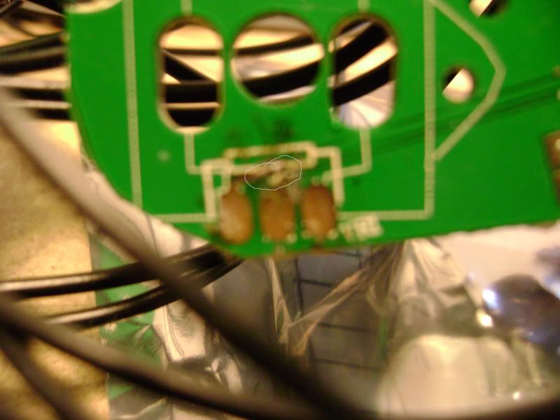
That didn’t work out very well. I was wondering if anybody can show me where I can solder for the middle and low so that I can get the trigger working. I’m not an expert in the electrical field.
Thanks
good news and bad news.
good news is that there is another spot you can solder to.
bad news is that is gonna be hard as hell for you since its at the Big Black Gloop. I traced it back to the 5th pad from the right on the bottom set of pads.
Thanks anything helps. How about the low?
wouldn’t that just be ground?
…great success!
Got a common ground 360 wireless pad this time and to make room I relocated the battery and left the analog sticks on instead. Thats 28 less points to desolder and 12 less points for me to fuck up attaching resistors.
Even so, I tore one of the analog trigger points where my 10K resistor was supposed to go and luckily hit the second point.
I guess I hit it because nothing goofy is happening…riiight? If I had removed the triggers and not used the 10K resistor what would happen?
This time I used solid core wire I recycled from some cable @ work and man…I absolutely hate that shit. So stiff and zero flex…never again.
grats! Sounds like you need to practice your solder/desolder skills though.
Not sure what would actually happen if you left the triggers w/o the pot or resistor, but it could register false readings. I do know if you remove the analog stick and don’t replace it with resistors that if you touch the contacts where the stick was, it will register a reading.
For sure, I’ve never soldered such tiny stuff…motorcycles and cars are one thing, a PCB is another world. That flux paste helped a lot, especially tinning the wires before I put them to the PCB.
I used a solder sucker with mixed results, it just didn’t always get all the solder off of those analog points and I would wind up ripping the contact off when removing them…sucks. Maybe my solder sucker is jacked up?
I know on my last failed padhack, the left analog stick registered a constant down state where one of the resistors/contacts must not have been making contact. No clue about the triggers…
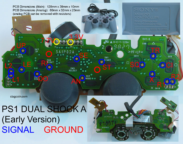
I just bought 3 ps1 controllers to mod, but they are the A series. I didn’t see them in the first couple of pages and I’m wondering if they are any good