i know i might get flamed since this has probably been asked before (but 141 pages is a lot to read and search wasnt terribly helpful)… but I have an xbox 360 late version controller and need to find out where i solder the 10k resistors in order to set my triggers to neutral… anyone have a pic of this?
I wouldnt get flux if you only doing acouple of hacks. How many Watts is your solder iron. I use a 15 watt from radioshack and i havent had any issues yet. Except for one LB contact. But that was 1 in afew dozen. And the most important thing is… tin your wires.
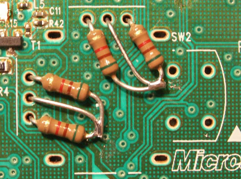
This is how I wired up mine. Uses a PNP transistor, a 10k resistor and 1k resistor for each trigger. When I ground the 1k resistor, the trigger button gets registered as being pressed.

where are those 1, 2, and, 3 things… are those just the 3 points where the triggers were originally attached?
and also, would it work with 2 10k resistors, from 1 to 2, and 3 to 2 on both sides?
Here ya go…
My iron goes up to 30…I already got the flux paste, it was like 7 dollars.
I just want to increase my chances of hitting those tiny d pad spots as much as possible.
I need to remember to tin the wires…but that burns off the rosin/flux so the paste will only help me get the solder off the iron and onto the spot I need it to go to.
ohhhhh ok… i get it now! i had read that before and now it makes sense…
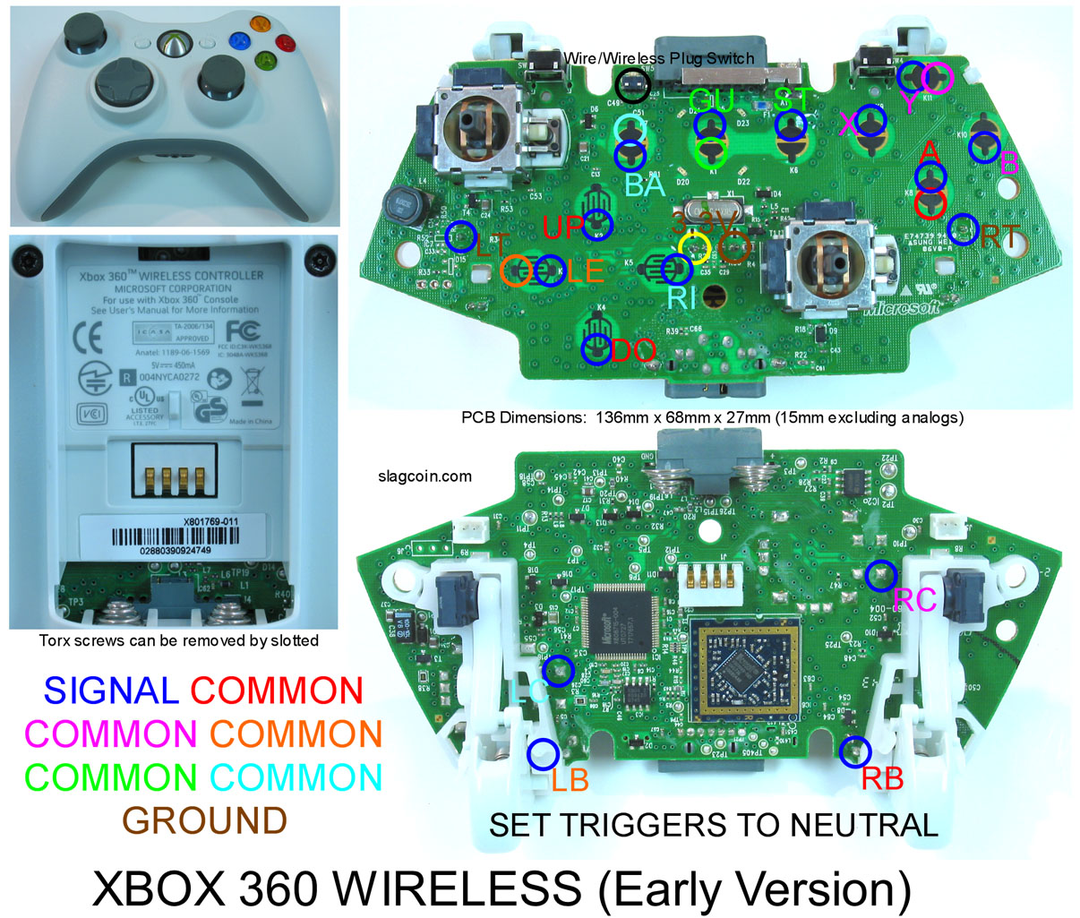
so i just need a 10k resistor from RT1 -> RT3 (same for LT) and then I just solder my signal to the RT2 place and ground to RT1?
Out of interest, are there any benefits for using this method as opposed to the usual 10k resistor method in the post below yours?
Let me know of the flux works out for ya. I was looking at getting the same stuff for the same issues.
can someone direct me to a HRAP2 pcb diagram. I skimmed through the pages of the HRAP2 modding tutorial and didnt see any diagrams. Will be doing my first Dual mod on this type of pcb. Thanks in advance
If you just want to neutralize the trigger, then the 10k resistor is all that is needed (same in my post and the other post). The extra stuff added is if you wanted to still hook up the trigger to a button.
I thought you could wire up the triggers for use with just 1 resistor per trigger?
I’m using a Flux by MG Chemicals. It’s in a pen form that you brush on. Let me tell you that having flux makes soldering SO MUCH EASIER. You can solder without it, but its much faster and much cleaner with it. You tin your iron, touch the spot, and BAM the solder goes right to it. I don’t think it’s a bad investment since it’s just a few bucks.
You can, but you couldn’t use ground to make the trigger register as being pressed. Because of that you cant daisy chain the ground to the trigger buttons.
I have an early PS2 pad that I’d like to use in a Dreamcast/Agetec stick. The pad I have is this one (http://slagcoin.com/joystick/pcb_diagrams/ps2_diagram6.jpg).
Unfortunately, I initially mistook the pad for another version, so have snipped off the membrane, thereby removing the resistor.
Can I add a resistor back on to the board, if so what spec resistor do I need (sorry, I’m not educated in electronics) and where should I solder it?
OH! I see what you mean now. Thanks for the info 
Doesn’t the ribbon slide out for that board? Anyways, from looking at that, you’ll need to solder a resistor with the value between 1k and 10k ohms on pin 7 and solder the other end of the resistor to pin 8.
I just did my first dualmod with a hrap2 pcb. The 3.3v power source is the black wire on the hrap pcb. As for figuring out which of the wires with qds were signal and which were ground, I first found a point on the PCB that I was sure was a ground point and then connected the hrap2’s ground and to 360 PCB’s ground and connected a wire between both pcbs power sources. Then I wired up all the signal points on the 360 pcb and connected it my PC. Then I touched one of the 360 pcbs signal wires individually to the all of the wires with qds from the hrap pcb, if it made a button press, the wire was obviously a ground wire and I left the qd on it. If it didn’t make a button press then it was a signal, so I cut the qd off so I could wire it up in a terminal strip with the 360 signals. Then instead of daisy chaining the ground, I just connected the original ground wires from the HRAP2’s PCB to the buttons. The only extra bit you need is a ground wire for the joystick.
Thanks for the info, I’ll try that.
Yes, the ribbon does slide out of this board. However, the HOWTO I was reading said to snip the ribbon in order to keep the small hard plastic tip (there’s a raised, hard plastic tip where it connects to the board). This tip can be used to assist in the solderless addition of your own wiring. If the tip is pushed in to the connector along with your own wires it adds pressure to keep them in.
I’ll try soldering a resistor to those points, thanks.
damn, i guess its a crapshoot, think i’d have luck just grabbing one off the shelf in a heavily trafficked store?
Why not try going to a local gaming shop that deals with used games and stuff? Simply ask them if you can take a look at there used controllers. If you feel lazy and don’t want to explain what your looking for, just say you want to examine them for cosmetic conditions. Take off the battery pack and take a quick peak at the exposed pcb and you’ve quickly found out if its the one you need or not.
Round #2
Had to toss my 360 wireless “common ground” PCB and start over.
So my other controller was a 360 wireless “non common ground” pad and I just finished the wiring (flux paste is godlike).
All my buttons work! …but my stick isn’t right.
Right and Down scroll Left (same as the Left Bumber).
Up and Left do nothing…
I did remove the analog sticks and put 4 10k resistors per side.
http://i50.photobucket.com/albums/f320/RDCXBG/SFAC%20Mod/StickRemoved005.jpg …like that X2
WTF should I be looking for?
I’m using a Seimitsu LS-32-01 which has the 5 pin harness and is common ground…is that my issue?