Thanks, [media=youtube]ZqHKe_donUY&eurl=http%3A%2F%2Fcoverlesstech.com%2Findex.php%2F2009%2F04%2F22%2Farcade-stick-modding-round-up&feature=player_embedded"[/media] will do the trick
However I canno’t seem to find the grounds for trigger buttons on slag’s diagram, or should I just daisy-link the grounds of the RT/LT sanwa buttons with another button on the 360 PCB one (say Y for example)?
Also according to slagcoin’s diagram its not possible to solder the LB without removing the plastic triggers (which means using 10k resistors for them not to mess up), isn’t there any alternative?
Can’t tell until you open the bundle and check the back of the pad, and even then there is a slight chance of being wrong: you can only be certain once you’ve opened the pad case.
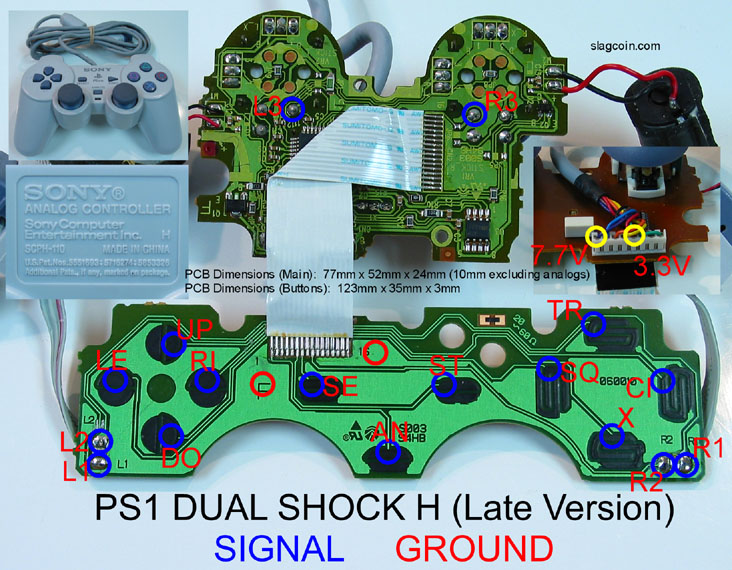
Well the late wired pads has common line for everything except for triggers, which run off true ground, if slagcoin is to be believed. So as long as you don’t intend on using the triggers, it may as well be common. I believe this is the same with the latest wireless MS pads, unless MS brought out a third wireless pad type.
Edit: BTW, I dunno if this helps, but a pad I recently received which was an early pad (stacks of common lines), had green packaging as opposed to the red one linked. This doesn’t really mean anything though, it could be regional differences.
while soldering this mornin, i ripped the contact on my back signal on my madcatz 360 4716 2008. are there a alternate points for the back signal, i seaarched and managed to find pics of alternate points for official 360 pads. (The back signal contact is completly gone :()
hey guys I don’t wanna do any triggers, and I’m conflicted cause I love the NeoGeo set up, yet I still want to play SF
so I was wondering if using one button twice will work
so the button layout for a 360 stick would go like this
A - B - X - Y
LT-RT-Y
thus when playing KoF or Blazblue I wouldn’t touch the bottom row, and when playing SF I wouldn’t touch the outward 4th button Y. I’m pretty sure it would work for a common ground
I have a padhacked PSX Dual Shock pad that I’m going to use for my stick. Came across a problem during testing. The part of the pcb that controls the analog movement is all screwed up and it makes my character jump backwards repeatedly. For games on PC, this is no problem because the analog doesn’t automatically turn on. For PS2 however, it’s not going to work due to this problem. On most games, it makes the p1 icon go crazy on the character select screen and then does the jumping thing again.
When I touch the area where the ribbon for the analog sticks used to be, the character will stop jumping, and either crouch or walk forward. I know that part is causing this issue.
Is there a way to “kill” the analog, but not affect the rest of the pcb so I can use it on PS2?
EDIT: It’s one of the original “A” Dual Shocks(not the ones that can be solderless hacked.)
Hey guys,
If im using a 2009 madcatz 360 pad to replace a fried pcb in a hori ex2, how can i set it up so i can keep the mic usable?
Does anyone know where to find a diagram of the mini pcbs on the top of the ex2?
thanks
Hi
I had a hard time finding any info on wiring a sync button, but last night figured it out. However, when testing the wires/solders (which worked btw) on wire popped off before I could hot glue and looks like it damaged the solder point.
What can I do? After reading all of the diagrams, I think I have the most recent MSFT wireless but have no idea if there is another point to solder.
I have done 3 wired controllers before, and always just do 2 wires per button…and avoid all of the daisy chain/common ground issues.
is the 2009 madcatz common ground, I want to make another stick, but I want a common ground and the store I checked only has 2009 models with the GAMESTOP logo on it.
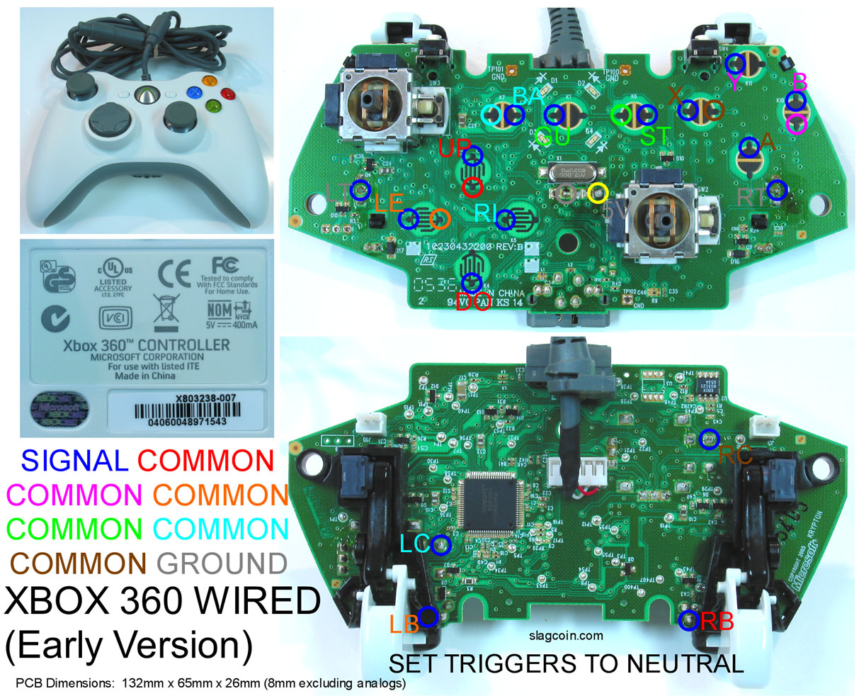
Is it possible use the same alternate point for 3 buttons on a non-common-non-CL wired 360 pad?
I’ve messed up with the D-pad front connections so I thought about doing this by “linking” them to a domino (or directly to each other as in a daisy chain), is it correct? Would I be able to use UP and RB simultaneously?
Alchemaga- yes the 2009 “gamestop” branded madcatz controllers are common ground, infact 2006-2009 gamestop controllers with the pointy grips are CG.
Hey guys, ran into a problem. Replacing a fried pcb with a 2008/2009 MC pad and for some reason the RB stopped working. I might of fried the contact(first time for me). So can your still solder to traces on these pads like the psx pads or is it different. This is the first time ive ever had trouble with a 360 pad, and its pissing me off.
I know the RB worked too. Before i could hit the actual RB button contact and it would register, after adding that second line to the solder point its not working at all.
Thanks guys
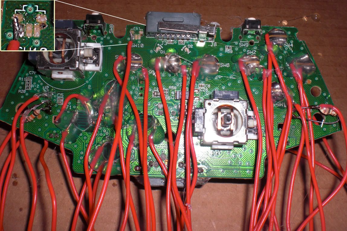
Edit- It was actually the LB that the contact points were fried. So i removed the actual LB switch and tried soldering there with no luck. So then i tried to scrape the traces and solder to them. One of two things would happen.
THe LB button would be open. In other words when i would go back to test the button it would be constantly activated
2)When i try to solder to the other trace, nothing would happen
So im stumped, and its really frustrating. If someone could please look at what im trying to do and give me some advice, it would be greatly appreciated
Heres some pics…Linked them because theyre big.


