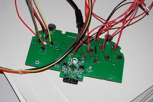
I tried the search option for this thread but it kept up coming with no hits.
Can someone direct me to a pcb diagram for the SF4 madcatz fight pad? Someone wants me to mod a stick using this pcb.
thanks alot
Dude what the hell???
RESIZE THOSE FREAKING PICS!
Jesus.
there is a thread about a stick using that pad here in tech talk… might check that out…
Thanks dan, found the thread.
http://forums.shoryuken.com/showthread.php?t=179270&page=2


Thanks for providing the pics Code Man65
I am using the madcatz model # BB-070 for the xbox 360. i was wondering if anyone knows where the 5v wire is on the controller.
hey guys, a friend that i modded a stick for using the 08/09 madcatz 360 pad is having some issues. He doesnt live by me so i cant take a look at it. I wired it using the bumpers and not the triggers. Hes had it for awhile but hes saying the LT is activating randomly. He opened it up and said everything looks good.
Any suggestions of what he should do?
thanks guys
sounds odd… just have him map LT to no function and that should stop it in game…
lol, thats true. but i want to fix the problem too.
if you didn’t wire the triggers, I can’t think of anything that would cause it to randomly go off… unless there is a wire in there somehow touching the signal for LT…
maybe put some electrical tape over the trigger solder points???
What’s the most readily-available common-ground 360 pad? Is it still a Mad Catz something or other?
Does anyone have a pic of a finished (soldered) mad catz arcade pad for 360? I am running into a bit of trouble figuring out how the ground soldering works? As in where to start -----> where to finish. I really appreciate anyone’s help on this. I used the pic on slagcoin for my reference to do the soldering for everything else, I just can’t figure out the whole ground wire process.
Searched and Searched and really found no explanation so heres my question.
I am modding mad catz 4716 wired controller for my pcb. impHave all the buttons wired and functioning properly, yet my character seems constantly walk backwards, my question is this due to the fact that I havent nulled the triggers using resistors and whipers method … or is it a sign that I should null my left analog ? Thanks in advance.
oh and check slagcoin.com for wiring diagrams for pcbs pretty self explanatory if ya got any questions send me a pm and I can prob help ya with the basics …
I think the wired official controller is cg, which you can get anywhere. The official wireless is common line. Most ppl go out of their way to get the madcatz though even though it’s not the most available.
Most likely is that the potentiometers for the triggers were removed, without tying the trigger signal high or low.
If you remove ANY analog potentiometer, whether for the triggers or the sticks, you MUST tie them in place with resistors if you want flawless performance. www.slagcoin.com goes over how to do it quite well.
Hey, quick question. If I’m hacking one of those Common Ground Madcatz controllers, I only have to solder one wire to the ground correct? I only ask because most diagrams seem to indicate two points for ground.
Can I link all grounds of a non-common-ground 360 PCB altogether?
I was thinking of this:
http://tof.canardpc.com/preview2/b4d2e8e8-066f-478d-bfd2-24b2c4feade8.jpg
Or should I use 2 domino strips (1 for joystick/dpad and the other assigned to buttons grounds only?)
I’d like to avoid having to cut traces on the joystick PCB, but bencao’s technique seems a little too advanced for me.
not exactly… you have a microsoft wired pad… the ground isn’t common… it does have a common line though… you can use the ground for the dpad to go to the joystick and all buttons except for the triggers… those have to be grounded separately… see this thread…
http://forums.shoryuken.com/showthread.php?t=161793&highlight=padhacking+360
So according to the thread you mentioned, I could do that, and then wire all signal wires to their respective TP?
http://tof.canardpc.com/preview2/6630a0cc-1cc1-4af6-9e3d-faaf8a008d99.jpg
I’m not sure I get the difference between a “common line” and a “common ground”…
Ah well, I’ve just taken apart my 360 pad and it seems I don’t have the CL version but the oldest one (the same as shown in slagcoin’s diagram).
So unless I use Bencao’s transistor technique I am doomed to hack my JFL pcb right?
unfortunately, yes. But instead of hacking (cutting traces) the pcb you can remove it as well. Search youtube for video tutorials.