anyone used this? is it cg? for the price of a mc cthulhu kit having a pcb wit ps and usb sounds pretty good
http://www.ggsticks.com/shop/product_info.php?products_id=83&osCsid=cb54a8b6d846ce3c05b2dd0a155498fc
anyone used this? is it cg? for the price of a mc cthulhu kit having a pcb wit ps and usb sounds pretty good
http://www.ggsticks.com/shop/product_info.php?products_id=83&osCsid=cb54a8b6d846ce3c05b2dd0a155498fc
Well from going off of what their PCB wiring guide says, I would say that it is cg.
for the price, that’s a good deal. but i don’t like how ps2 & ps3 have different default mapping.
ok, i just finish my 1st dual mod, a MC Cthulhu with Mad Catz Retro stick, which works great, i want to do another one, i just picked up a Joytech Neo Se 4716-1 Ver A pad, i’ve read around and know it is CG, but i want to use the triggers, everything i’ve read is for Ver B or later, do i need to use 2 x 10k resistors and an NPN per trigger (like ver B), or just 1 x 10k resistor per trigger( like the retro stick)? i really want to use the 8 button setup on this new stick too.
thnks in advance
didn’t notice the wiring guide (long day of being oblivious i guess)
yeah, that is pretty stupid mapping
I have a 2009 MadCatz 4716 Ver. E PCB and no matter what I do I cannot get A or Y to work, the points are not shorted or damaged and I have tried switching soldering points for each button. The PCB is part of a dual mod setup along with an MC Cthulhu and an Imp, and as far as I was able to deduce the problem lies solely with the MadCatz PCB. Can anyone shed some light on why all the other buttons were so easy to get working yet these two absolutely refuse to cooperate even though they worked fine when I tested the whole, complete controller? Are there alternate solder points I can try? I am just about to finish up this mod but these two buttons have me pulling my hair out.
ok after reading through the thread again, toodles states that the pad is not CG, it states that the diodes on the back are not common ground, can i get clarification of this, i’ll post pics of the board 2mro, i’m out of town.
can anyone confirm if a Madcatz black 4716 controller is compatible with the MS wireless headset?
Wireless headsets connect to the console, not the controller…
yes and I’m wondering if this controller ALWAYS reports a headset plugged in which would prevent a wireless headset from syncing. I cannot find a definitive source.
Hey guys, today i messed up the PCB of my Hori EX2 and we got a big local meeting here at the weekend so i need to have my stick ready by then.
Im planing to buy a new wired Xbox 360 Controller and solder it to my existing case with Buttons/Stick
Im using Seimitsu Buttons and a Seimitsu LS-32.
If im correct the Stick is a NON-COMMON-GROUND Stick because it uses 2 Connectors on each Switch instead of a five Pin Connector with 4 Signals and one Ground.
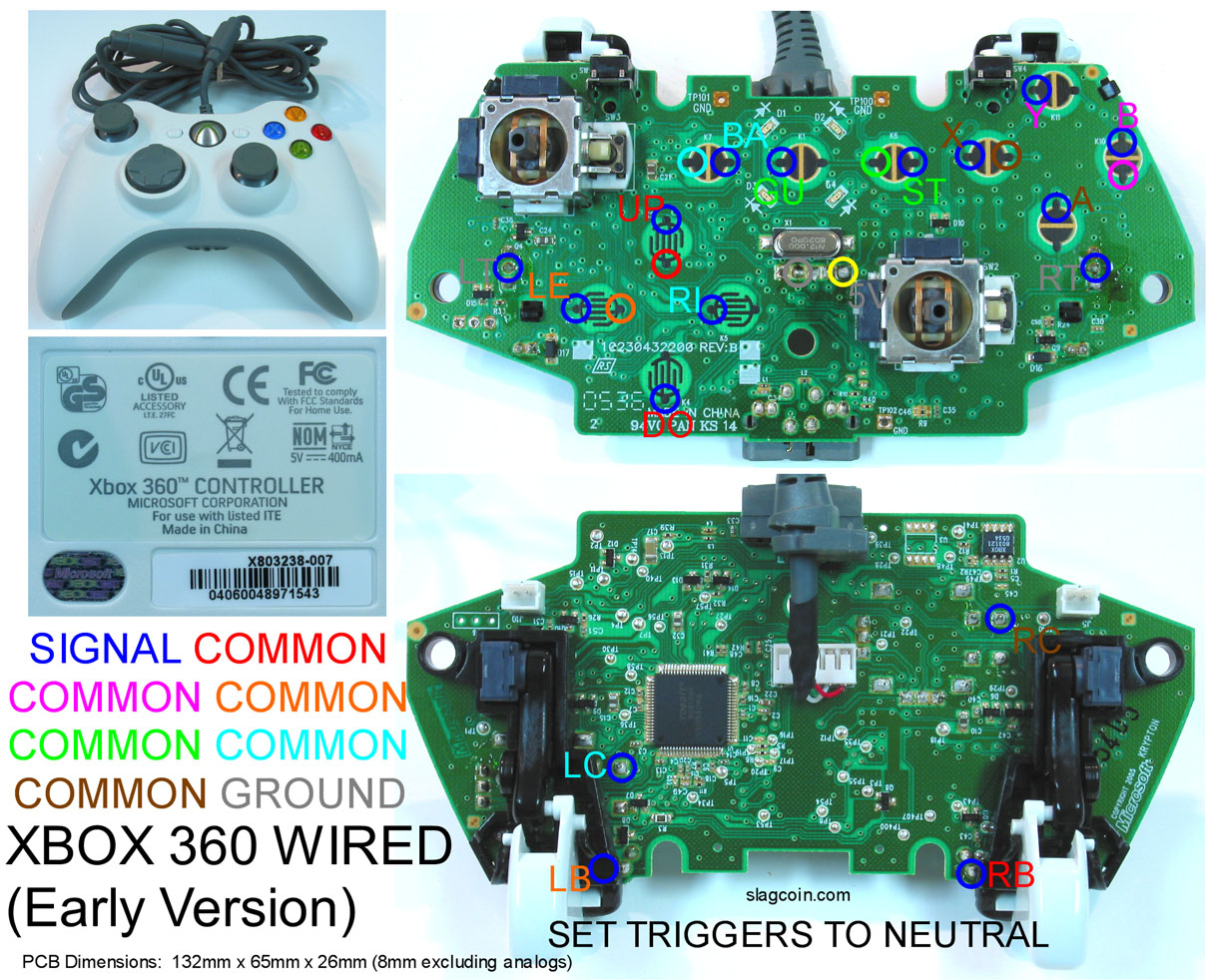
So im right when i say that i can basicly wire cables to the marked spots in this Picture.
http://arkadesticks.com/hackedpads/Xbox360wired.jpg
Then solder the end of the A Button to one of the Pins from the Seimitsu Button and than just solder the corresponding Ground to the other Pin of the Button? Is That right? And does the same go for the microswitches? Does it matter wich pin i solder the Ground/Signal to at the microswitch?
How is the mapping on the Stick?
B X Y
A RB LB
This should be correct or did i mix RB/LB?
Thanks in advance
Thomson
That is correct, the LS32 is by default, non common ground.
However, you can easily convert it to common ground by chaining together the same pole from each switch.
You need to figure out if the PAD is common ground or not.
To do that, use a multimeter in continuity check mode, and touch the probes to the ground connection on two different buttons…if there IS continuity, then the pad is common ground and has to be wired as such.
As for the switches on the stick, just be consistent…look at each switch and assign one connection to be #1, the other #2. Do this for each switch in a consistent manner, then use all the #1s for ground (or the #2s, it doesn’t matter, but what does matter is that each switch is handled the same way).
Yeah thanks, that helps alot,
To sum it Up,
Common Ground Pad :
For the buttons i wire the Button AND the corresponding Ground to one Button (Signal to one Pin, Ground to the other)
For the stick, i connect the switches to create a common ground nad use one ground of UP/DOWN/LEFT/RIGHT and wire it to one of the grounds at a switch.
I made a picture of it
http://img35.imageshack.us/img35/9892/commongroundpad.jpg
Non Common Ground Pad:
Buttons are the same s common ground pad, 2 wires for each buttons (Pin A to Signal / Pin B to Ground)
For the stick i use the same method as for the buttons, so 2 wires for each direction?
And by the way is the key mapping correct? RB is the middle button and LB the outer one? or did i mix it up?
EDIT:
I read your post again, so if the Pad is common ground it also applies to the buttons and not only to the DPad right? so i basicly can do the same to the buttons (wire each button together and use only the ground of one button) right?
Yes, your diagram looks like it will work.
In my experience, most pads tend to either be all common ground (dpad and buttons) or not.
But I definitely recommend testing the various grounds for continuity (to see if they connect) to make sure.
Example: My MadCatz pad has a shared common ground for X, B, A, Y, LB, RB, Start, Select, and Guide.
So my ground chain touches nine buttons: x, b, a, y, lb, rb, start, select, guide.
Here is that pad…see the black ground wire coming off the A button? That ground is shared between the 9 buttons I listed above, but the DPad had a seperate ground, that was only shared between D,U,R, and L.

I am royally confused on how to pad hack the Mad Catz Retro stick.
Where do I put the grounding wire if I have a Happ Perfect 360 stick.
Do the A,B,X,Y buttons run off the same grounding as the triggers.
ANd where is the grounding for the Start, Back, And Guide button?
Also, whats with the setting the triggers to neutral?
That looks like an official wired “early” (slagcoin terminolgy)/matrix (rdc of xbox-scene terminology) msxb360 pad. None of the wired msxb360 are common ground. For your pad, the finished product may look something like this.

Help please.
I got a small event tonight and I want to make sure what I’m doing is right before I go to it.
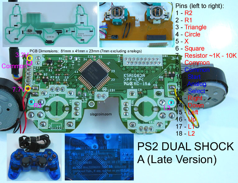
Hey, I’m having trouble with a Dual Shock 2 Version A (Late Version). I’m following this diagram but I cannot find the common ground. I’ve tried with the 8th pin which should be the 4th pin on the second row, but no luck. However, start/select/analog works fine with their own ground. This controller works when I plug it back into the ribbon cable.
EDIT With a little digging, I was able to find an old post by Toodles. A 4.7 OHM resistor between ground / and VR1 (3) did the trick.
Thanks
For Madcatz xbox 360 pad, is there a way to remove the analog stick from the board?
Yes, desolder the analog sticks and solder some resistors.
4 for each stick.
2x for horizontal movement
2x for vertical movement
see my post here