ok thanks I will replace it. Since I have the chance is there a tip that is better for PCB work? I’ve just been using the default one that came with the radio shack soldering iron.
hey toodles, any chance you could have a quick look at my pic 7 posts back, and let me know if i have ruined my joypad or if i can save it, i have another pic there of my other joypad (sticker on the back) that i haven’t seen before, i am sure it is just 1 of the newer common ground wired pads but any chance you might know ?
http://img42.imageshack.us/img42/8873/dscf7082.th.jpg
http://img42.imageshack.us/img42/771/dscf7083.th.jpg
http://img43.imageshack.us/img43/5157/dscf7085.th.jpg
this is my first attempt to do anything with a 360, so i am using a madcatz pcb. the second picture is the wires for the left bumper and left trigger. can someone tell me if i need to take that yellow part and the bumper off? thank you all for your help.
the yellow thing is only taken off during the process of wiring the PCB to the use the triggers. it looks like you want to use the triggers but it’s not as easy as soldering a wire to the trigger signal as you have done. you should take a look at this thread.
I have a question, I dont have a 360, is there a way I can test the guide button? Should be wired correctly but when I press the guide button (even for stock controllers) nothing happens in windows. I’m using the official MS drivers. Should be wired fine, I have a multimeter lying around here if that’ll help me.
im not going to use them… so im not going to worry about it.
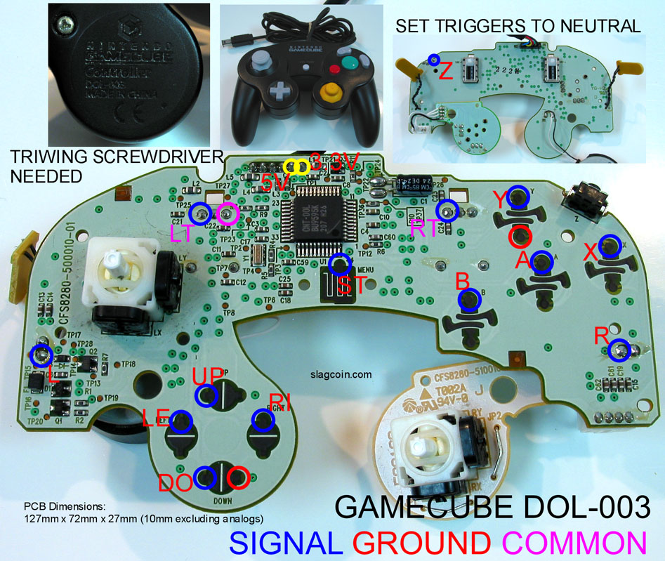
Interested in wiring up a GC pad but can anyone tells me the difference between the common and ground
http://www.slagcoin.com/joystick/pcb_diagrams/gc_diagram1.jpg
You’ll notice ground and common are written in certain colors and then the buttons are written in the same colors. Buttons matching the same color as the word “Ground” all use it as ground. Ones matching the word Common use it as ground.
In your case it means that all the buttons use the red Ground except for LT and RT which use their own common ground (the purple one).
thanks for the help
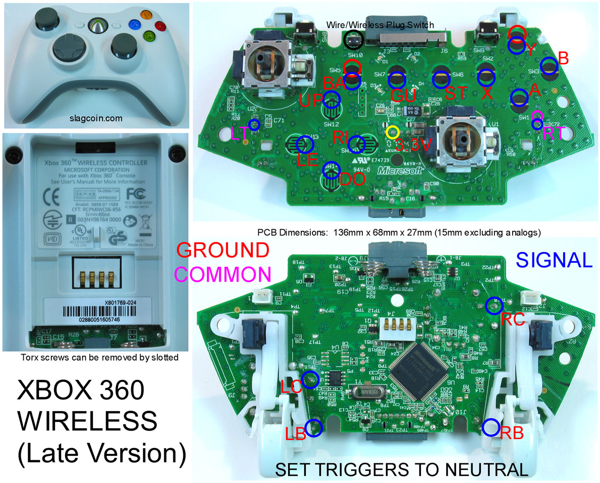
I have a question. In a common ground 360 wireless pcb, can any pad opposite a signal pad be used as ground or only the ones circled on slagcoin’s diagram?
PS1 DS Pad Hacking Help
I purchase a stick of of EBay and I had to re-do the wiring for the PS1 DS. In the process I managed to destroy solder point fir the R1 button. Is there another point where I can get this connection from?
I’d also like an answer to this. I use the MS drivers and have never been able to test the Guide button on PC. Some people have claimed they get a pop-up in Windows. I’ve never experienced anything like that.
Which version of the DS pad did you use? Was it a little copper pad that lifted?
I think you can do it with a continuity test on a multimeter. However I’m not quite sure how to work mine. I tried setting it to the setting where it has the arrow and a plus sign which I believe is the resistance test. I read that continuity tests are not directional but when I do it I get 1 (meaning no connection) when I have the ground lead connected to the ground and the signal lead connected to the signal lead and I get a reading of about 550-600 when I reverse the connections so I’m not sure if I’m doing it right. I’m using this cheap multimeterwhich unfortunately doesn’t have the beeping continuity test.
Here are the drivers I use: http://www.mediafire.com/?sharekey=a854f7209e045bf5ed24a2875c7fa58ee04e75f6e8ebb871
Hey i know the dreamcast hkt - 7700 has input lag but what about this controller.
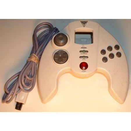
has anyone experienced lag with this controller
I was just wondering about using the L and R triggers for a 360 Wired Pad(late). I got the resistors but I have no clue where to solder them. Help please?
Found my answer, its yes.
ok, my friend made me a stick about 5 yrs ago, and he used arcade parts, all i had to do was get him a playstation controller and a box. we’ll i’ve moved a lot since then some where along the line the cable to plug it into the playstation came off, i figured i’m modding my hori ex2 why not fix this too, now i don’t remeber the brand of the controller and i’ve looked everywhere for it, but i did find this, it’s a picture of the pcb, i just need some help figuring out which wires go to which points? any help would be appreciated.
http://img29.imageshack.us/img29/6/controllerpcb.jpg
i know that there is only 7 points, and if they are labeled from Left to Right
1 is ground, and i think 4 is data but other than that i’m lost.
can a play n charge cable be used to power a wireless 360 pcb without a battery pack attached?
Edit: Yes it can. In essence, it just becomes a wired controller.
The only pads with lag are the ones with triggers, those six buttons will have no lag.
Which version of the DS pad did you use? Was it a little copper pad that lifted?
[/quote]
It is the PS1 DS H, I think. I basically followed the R1 button path a little and scraped off the light green protective coating to exposed the copper. I then soldered to that. It was not easy but it works.:wgrin: