Yes, its the same for the 2009. Thanks to Kyle for mapping it out for us.
I’m on my very first attempt at hacking a pad, and I’ve run into a problem. The pad is the cheapest ebay pc usb-pad available, and seemed easy to hack. The problem is with the directional pad which seems to require two different grounds. All the buttons and 2 d-pad contacts work with GND1, but the remaining 2 d-pad contacts seem to require that I use GND2. How do I go about wiring that to my Seimitsu LS32-01?
I know pretty much nothing about electronics, so please be very specific :rolleyes:

need some help on this as well. Thanks
I was wondering if I should just order a standard LS32, the one without a pcb. Would that solve my problem?
Hello all,
I have the new version of GameStop madcatz xbox360 controller and I’m trying to neutralize the left analog stick but i’m having some hard times. It’ll just go crazy when i plug it into my xbox. any help would greatly appreciated.
Here’s what I did:
After opening the controller and scratching off the black stuff off, do you generally solder the wire onto the signal side of the button or on the ground side? Or does it depends?
That’s not the question you want to ask; you need to learn how the wiring works. Go to Slagcoin.com, it’s an excellent stick-making tutorial with a great page on PCBs and wiring.
Basically, each pushbutton needs to be soldered to a ground and a signal, but depending on the controller (if it’s common ground or not), you might be able to just daisy chain grounds together, or you might have to solder all of them to their own ground.
You want a common ground controller.
thanks for the link & fast reply. 
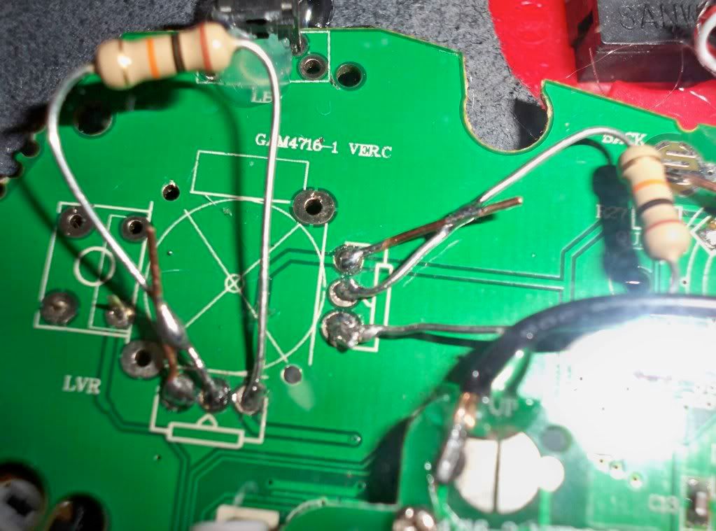
i did the same thing only with the 2007 late model. where are the alternate solder points without having the scrub off the enamel of the traces too much?
Looking for help and advice 
Hi guys long time reader first time poster. Let me start out by saying what a great community this is for all gaming needs.Alright let me get started by asking a few questions, i have a modded stick and about to a tempt this PCB padhack, i have read most of the posts on this padhacking topic but i am still wondering about a few this hope you guys can answer my questions.
-
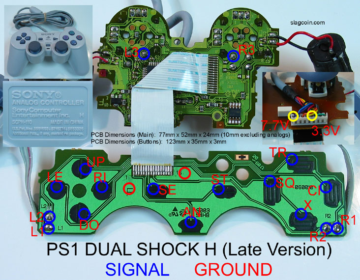
I know the PSX (Playstation 1) DS (Dual Shock) has the best compatibility with all brands of adapters and such, my question is that when i am a tempting this mod pressing down on the psx ds controller L3+R3 will it work like a ps button on the ps3, i know for the ps2 dual shock it works like a ps3 menu button.
-
I have seen a post on this topic about the soldering points and which button is which, i still don’t understand the common and ground part of the controller pad, like i checked this site http://www.slagcoin.com/joystick/pcb_diagrams/ps1_diagram9.jpg on the PSX Dual Shock Controller picture i see the 2 ground near the area of the psx ribbon cable what does that mean. i am not sure how the grounding thing works on the pad can someone explain it me thanks.
-
What does 7.7v and 3.3v do anyways, also if i hook up every button on the psx pad on my arcade stick modded with happ buttons. Will i be able to use the analog stick to play games instead of the digital pad. thanks.
Sorry for the bad english hope you understand what i am trying to say.
I have the x-arcade modded with happ buttons and bat top joystick looking really good. i know the x-arcade is crap but good for modding, any who i am planning to change the PCB of the x-arcade to dual PSX PCB. anything you guys think i need to know before i change the PCB or even start a tempting this mod. thanks.
Several searches, not much luck so posting here. I’m working on an official DC pad hack and I’m running into problems with the stick itself and the triggers. I used this as the guide :
http://arkadesticks.com/hackedpads/Dreamcastofficialpad.jpg
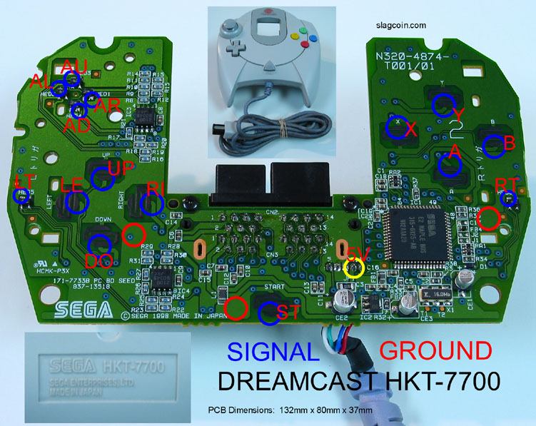
I’m guessing for the triggers I need to completely remove the stuff that’s on there already, don’t think I did a good job there so hopefully another go at those will solve that problem. The stick however is always going left vs neutral once it’s all together and plugged in. The JLF wire harness and all are daisy chained to the ground to the upper right of the down button :
http://slagcoin.com/joystick/pcb_diagrams/dc_diagram1.jpg
I’m going to open it back up and resolder the left signal to make sure, but I wanted to check if it’s okay that I’ve got the joystick and all the buttons daisy chained to that one ground or if the joystick and buttons should be separate? If that’s okay, what might it be - just a bad solder job on that signal?
Thanks so much for the help.
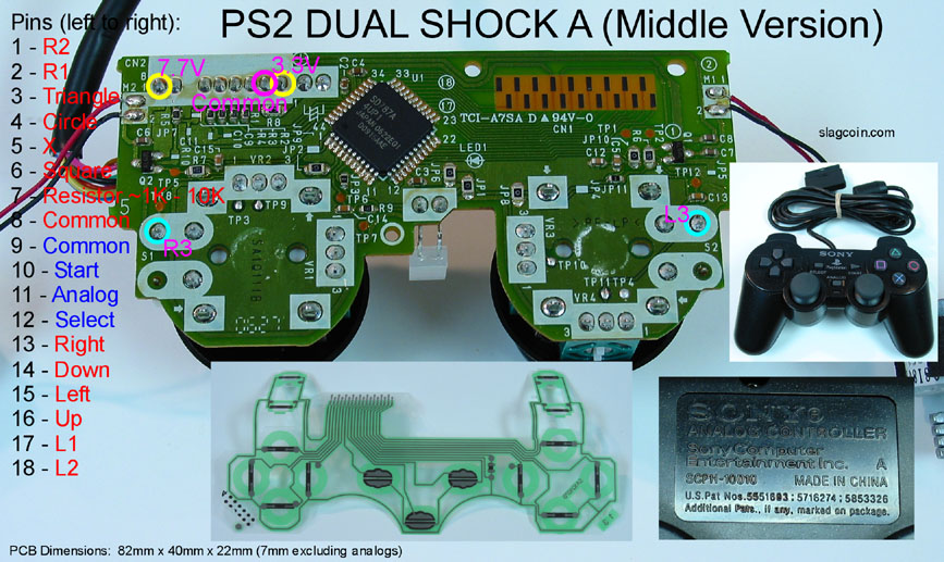
Can someone please tell me why i should “avoid” the PS2 “H” PCB. i have one lying around the house and wanted to use it for a stick.
Okay, so I have a M$ wired official pad and want to wire up the triggers, now to do that I have to remove the pots and solder a 10k resistor to the wipers and solder my signal to that and the ground to the ground of the trigger or common ground?
Does this diagram represent what I have to do???
If anyone wanted to know about using the imitation Sega Saturn pcbs, i just finished wiring to my stick to use on PS3. And all is well !
http://g.imagehost.org/view/0707/c9af_1
Its a very straight forward board. The solder points are tiny and there are no points on the back at all but because the whole board is on one common ground, the trick was to break the ground trace at each switch point and gently scrape back the entire switch surface being careful not to scrape the ground surrounding it. This gives you gives you plenty of surface contact, without it you will suffer and there is a possibility of the solder being pulled or knocked off and pulling up the trace with it, then your screwed because there are no other points to solder to as the traces run straight into the chip.
Btw the two shoulder buttons are L1 and R1, the two end buttons in the 6 button row are L2 and R2.
Unfortunately i don’t have a pic, because i don’t have my camera and my camera phone makes close shots look like something the dog threw up. But the ground is actually the only two black wires on the only pin connector on the board. If the wires are not black on your version, then you only need to see that all the other pins have a trace leading to the chip, whereas the bottom two do not have a trace and are sitting in contact with the surrounding ground metal that covers the entire board.
But anyway it works perfectly for both PC and PS3, and i paid 10 for it
Sorry for the late response. I tested that diagram on my wireless common ground MS controller and it works. I believe its the same thing for the common ground wired versions.
To test I went ahead and soldered my resistors and just touched the ground and signal with a wire with the controller connected to the xbox and it worked fine.
So this is the remote i have and i was wondering if the reason for the AVOID is because its harder than the rest because to my understanding it looks as though i can just cut the traces and solder to those cut traces although they would be very small.
If someone could verify this, that would be great.
thanks
Actually the same one i got, i works but the soldering points are to small and also its too close other then that it’s moddable
thanks thats what i thought the only problem was, im pretty good at soldering so if i cant find an alternative ill just use this one
Im unsure if this will work, but i have a PS1 Controller (Rev A, Early) i want to padhack with a X360 Wireless Controller. they dont have to bridge each other.
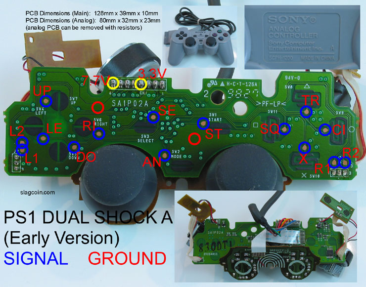
Im unsure of how to remove the Analog sticks. Can i just unsolder them or do i need to put resistors on them? (If so, what types of resistors do i need?) Im assuming i can just unsolder the rumble motors.
Also according to the diagrams, There are two places im suppost to ground, but i dont see any leads to that spot. As well, the 7.7v and 3.3v… im not too sure about that, is that already done since it is a connection from the PS1 Connector ?
im using a PS2 - PS3 adapter to make it all work out (For the PS1 side).
Any advice would be great.