*The "padhacking" thread*

It will lower the battery life yeah.

I looked at the back of a 360 pad and it says 450ma, I am assuming that is for the standard battery pack because the battery pack has no markings. 20 miliamps is about 5% of your battery life per LED.

Yes.

Yes, but I don’t know how to do it off of the top of my head. Maybe make the guide button also an on/off switch for your LED and battery pack somehow, I am really not sure.

Cool, I grabbed a bag of LEDs and a bag of resistors off my bro today, so I’m gonna have a crack at it tonight. Thanks again, I’ll let ya know how it goes.

mad catz #4736 micro controller

Anyone use a MadCatz #4736 Micro Controller for their stick? Cant find the pcb diagram for that controller.

http://f3c.yahoofs.com/shopping/3086491/simg_t_o19514536641951453664gif?rm_____DY5x4XxaE

I searched like crazy already.

Thanks

Question before I go to bed.

Since my LS-32 already has daisy-chained grounds, I’ve decided to use my Early non-CG Xbox pad ( http://slagcoin.com/joystick/pcb_diagrams/360_diagram5.jpg ) for practice, and then I’ll turn around and buy a late version 360 pad when I’m comfortable with my padhacking skills.

Fortunately my roommate already has a multimeter that can do beeping continuity testing, so my first order of business is to scrape away at one signal/ground combination and test for continuity on the copper contacts themselves. These pictures are poor quality, but you can see that I’ve scrape to the copper contacts for the ground and signal of the Y button:

However, when I perform continuity testing on the two contacts after connecting pad the the xbox and giving it power, I still show an open circuit. Is is possible that I’ve not scraped enough covering away, or that I’ve hurt the contact, or that I’m doing something else wrong?

I was wiring up a Madcatz 4716 pad(2008 model) and I riped the copper pad and a lot of the trace up for the B button. Is there an alternate point I can solder to for the B button?

how do u wire the sync button on the xbox 360 common ground wireless controller?

I’m on the same boat. I’m trying to follow this CG wireless diagram from slagcoin but when I hold the black wire from the multimeter on a ground pad (circled in red in the diagram) and the red one on a signal (circled in blue) I get no beep. But if I hold the red wire on to the opposite pad (not circled in the diagram) I get a beep. I assume I’m doing something wrong as I have no experience with continuity or a multimeter.

Also, the diagram shows a pink circle labeled Common, what is that for?

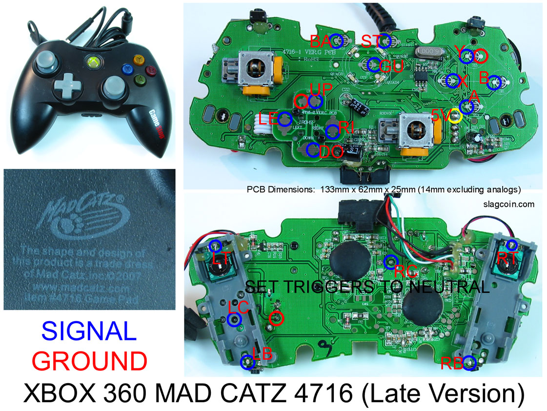
Current Pad: Gamestop black Xbox 360 pad 4716 2009
GAM4716-1 Ver E ROHS (printed above left analog stick)
4716-2 Ver C (printed on D-pad)
MadCatz 2009 (printed on back of controller)

Joystick: Sanwa JLF-TP-8YT
Pushbuttons: Sanwa OBSF-30 & OBSF-24

Arcade Stick: Tekken 5 Anniversary Ed. PS2

Extras: Multi-Console Cthulu board & DPDT switch
Padhack Attempt: http://www.flickr.com/photos/38050510@N04/3499646016/
Noted: I am unable to remove analog sticks due to both being hotglued underneath.

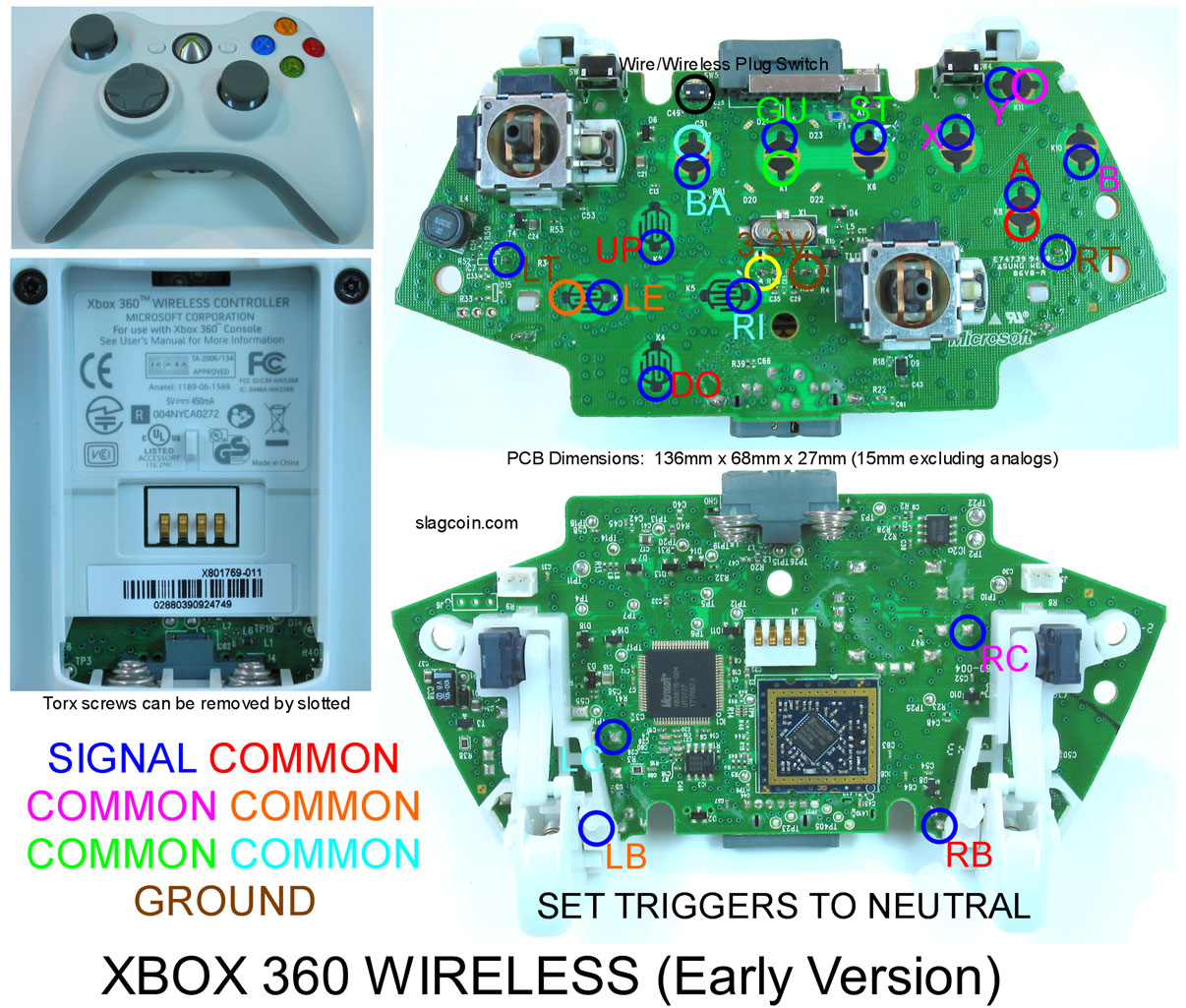
First of all, my goal is to convert my PS2 T5 arcade stick to be playable with PS2, Xbox 360, & PS3. I tested for ground continuity on all points (d-pad and buttons). Currently, I am using the “UP” button’s ground point as common ground per slagcoin’s 360_diagram3 image. http://slagcoin.com/joystick/pcb_diagrams/360_diagram3.jpg.

Said ground line is connected directly to a ground point on the Cthulu board. The Xbox 360 Gamestop d-pad and button signal lines are connected directly to points on the Cthulu board (piggybacking via A-H & 1-9). Push button signals are directly connected to the Cthulu board. I daisy-chained or linked all push button ground points (also connected to Cthulu board). Push buttons activated and deactivated properly during a “Game Controller” properties test under Windows XP.

The start button (button: 7 in “Game Controller” properties) is the only permanently active button & no joystick directions work correctly during a test. For example, the Up button may seem activated for a few seconds then deactivates without any interaction on my part. Also, down, left, and right do not activate or deactivate.

The select button did the same thing before I noticed a cold solder joint within the ground “chain.” (which I fixed)

Any thing I am overlooking in my setup? Should I connect all Gamestop controller grounds (UP & Y button) to the Cthulu board? Like this:
http://picasaweb.google.com/wliu0912/PrehackedPads#5282843023799314882

:Note:
Voltage and ground for Gamestop pad & Cthulu board are connected together via points “A” & “C” (360 piggyback area) on Cthulu.
USB data -/+ points on Gamestop pad are connected to switch #2 on DPDT
USB data -/+ points on Cthulu board (from row #2 spots “D” & “E”) are connected to switch #1 on DPDT
DPDT center points go out to USB cable

My PS2 cable is connected via row #1 (pinout is as follows)

Pinout | Row #1

Brown -2- CMD | B
Orange -5- VCC | V
Black -1- DAT | C
Red -4- GND | G
Yellow -6- ATT | D
Blue -9- ACK | F
Green -7- CLK | A

help! i’m using a saitek 3200 pad for my stick and though it looks like everything works fine the pad randomly dies on me after some playing, either some or all buttons stop working, the time varies and after unplugging and plugging it back in everything works just fine again. sometimes i play for over an hour and everything works fine. anybody got an idea what’s the deal?

Is there a way to solder LEDs to a PS3 Sixaxis pad? I want to put in my own LEDs… how would I do it? Would I need to remove the current LEDs? Can I just solder to each end? What kind of LEDs would work?

Anyone know?

I’d like to know too since that’s the next pad I plan to hack.

That’s the wrong diagram for your pad. Use this instead.

is the 2008 diagram the same for the 2009 controller? i jus picked up another madcatz jus like his and wanna make sure its usable before i rip it open? from his pic i can see its still common ground i’m assuming. maybe ill jus rip it open n start testing

edit, i just opened mine up and its identical to the 2008 diagram.

ovega, your soldering is all wrong on that pad. only one hooked up right is the right pad and x, y, b on the buttons and back. redo your whole hack with the diagram above

I’d be glad if someone could help. Is it possible to do the same soldering job with the ps1 scph 1080 H series, but not dual shock? I opened it up and its similar on the inside. Now the directions, select, and start have the similar layout, but the 0 X triangle and square have a weird circle and line pattern, with 4 spots to solder and 3 on some.

Also the L and R’s have 3 metal knobs, but arranged side ways not up and down, and it doesnt say L1 or anything on it.

Oh btw the controller only has one L and one R button.

Does anyone have a guide to solder this pcb?

What do you mean it is all wrong; please clarify. Should I have soldered the “dots” on the signal pads only and not entire pad area (for example d-pad)? The “X, Y, A, B” buttons activate/deactivate properly. My problem involves the start and directions (up,down,right,left).

As far as I can see, there is no difference between my attempt and the 2008sp4 diagram; what do you mean it is all wrong.

i’d be happy enough if somebody could even just guess what it might be. the soldering is holding up, and i just don’t know where to start… maybe i messed the triggers up…

vega, maybe you should try using the ground from one of the a,b,x,y buttons for buttons, and use the ground from up,down.left,right from the joystick. don’t know if that really matters but thats what i did and zombie does as well.

and make sure rt/lt are not sitting active. one question tho, did you scrape the traces before you soldered? on the madcatz pads you don’t have to do that, but it looks like u have a crap load of solder, or you scraped it. also, go over all your solder points n make sure no solder is touching its grounding pad next to it. even the slightest button doing so can make the pad act up

So does anyone have any answers to my PS3 LED question? Can I put in my own LEDs? What voltage do I need? Do I need to remove the current LEDs first?

Okay, nevermind… I answered my own question. I used a digital multimeter and measured the voltage across the LED to be 1.8 volts. So I picked up a pack of four 1.8 volt LEDs, removed the current LEDs, and soldered my own in and they work fine…

Next question…

I know you can cut down 360 pad and surface mount the board into a PS3 pad… Which 360 pads can be cut down? And which PS3 pad can I solder it to?

hacked a street fighter game pad and i have lag issues with the a button. i have tried different buttons, grounds, and wires. it still lags, any suggestions?