I think my pad is fried, I found that the white cable from the usb on the 360 PCB broke off so I resoldered all the wires in the main cable but that didn’t help at all. I still have no power to the board.
With analogue sticks, 2 of the 3 solder points for the axis have traces running through them, the other however isn’t connected to anything, should it connect to the others or is there a trace within the board that might be damaged?
The black stuff I believe is there to stop corrosion/oxidation, no you can’t solder to it, it will probably come off on your iron and ruin the tip. You need to sand the black epoxy off.
The danger of gluing is that it will move around and stop working on you, it is not a permanent solution.
Hey dudes, I just got a couple of simple questions, sorry if they’ve been answered already but this thread is pretty large.
Just so you know, I’ve got 3 hacked pads here, fully functional that i did without any help whatsoever, just opened them up and went for it… So I ‘kind of’ have an idea of what i’m doing…
I have a hacked PS1 digital pad, can I fuel a couple of LED’s off this?? They don’t have to light up on button pushes or anything, can be constantly on. if so, how easy is it?
I have a Dual Shock 2 sitting around, is it worth having a crack at hacking it to save a few bucks or not worth the trouble?
Any good resources on adding lights to my sticks would be well appreciated, as I got no idea about how that shit works…
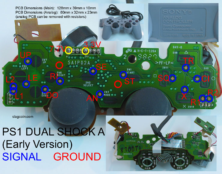
Basically what you need to do is find the 3v point on this pad. Then you are going to get your LEDs, and then you need to use an LED resistor calculator (there are a bunch online) to figure out what ohm resistor will bring the 3v down to a safe level for your LED. You just wire one wire to the 3v point, then the resistor, then the LED, then the other end to the ground.
BTW, make sure you wire the ANODE to the 3.3v point, which is usually the leg of the LED that is longer, and the CATHODE to the ground.
Ugh, so I’ve been working on a dual pcb mod (madcatz retro arcade + ps3 cthulhu + dpdt switch). I have all 360 signals piggy-backed to the cthulhu (A-H & 1-9 points) and dpdt all wired up, but when I plug it into my computer I get nothing (360 & PS3). I’ve been checking continuity between the VCC, D+, D- & GND and noticed all points except for VCC connect from the connector of the USB cable to the 360 USB points. I tested continuity from usb Red-V point to the A point (360 VCC) on the cthulhu and get an open loop. Blk-G to C point went through fine. Is this what is causing the pcbs not to detect on my PC? I’m stumped as to what to do next
*Solved! turns out I didn’t solder the USB Only jumpers together >_<! Works like a dream now!
Hey, thanks very much for the quick response. So the cathode will wire directly to the ground? I don’t need anything between the LED and the board on this end? Can i use the common ground my buttons and stick are wired to?
To be honest this was just a passing thought, and i’m fairly clueless, my brother has a bunch of different sized LED’s so I’ll see what i can find and take it from there.
Right. I could be wrong but I seem to remember that you can wire the resistor behind or after the load (in this case your LED) and it will lower the voltage either way, but I could be misremembering high school electronics (Toodles might be able to correct me). But if you put the resistor between the 3.v and the LED it is for sure going to work.
Doing multiple LEDs could be tricky, so I don’t know how many you want to do.
You can use any ground, shouldn’t matter.
NP. If you don’t have info on the LED’s requirements, as long as you don’t mind replacing it the worst it will do if you feed it too much juice is burn out prematurely. But if you have resistors around, keep adding resistance until you notice the light gets dimmer, and then give as much resistance as you can until the brightness is enough for you.
There might be some way to properly find out what kind of power you need for an unmarked LED, but this is a joystick not rocket science. :tup:
For sure. If its only a matter of burning out LED’s then I’m confident in having a play around with it. Ultimately I’d want one for each button (6), so if anyone can elaborate on how I’d go about that it’d be cool… otherwise I’ll just poke around the net/play around see what i can come up with…
Okay, I have opened 2 controllers so far and I am baffled.
The First controller I opened was inside a case that had a backing that is identical to the backing on the (early) Xbox 360 wired controller according to slagcoin.com’s diagrams.
The second controller I have opened as the exact same back as the (late) common ground 360 wired controller but when I took the PCB’s out they are identical!? wtf!
Please someone tell me, are these common or matrix ground. I have a multimeter but am not to sure how to test for common ground. Here are pics of the controllers
So, I bought a presoldered PCB and the left direction solder isn’t working (I’m positive, I’ve tested extensively). There is glue over the solder. Any advice for fixing this? I’ve got a soldering gun and plan on heating a knife to remove the glue.
After seeing all those custom-made sticks, I decided to try to create my own. First of all thanks for this great thread, I already learned quite a lot from it
I have this PS1 controller:
I already took it apart and tested it by connecting ground and the appropriate points with a wire and it the PCB seems to be working. If you look at the PCB diagram, the marked ground is just a place on the board without an actual solder point, do I have to scratch off the surface there first? And what about the signal points, can I directly solder to them?
Sorry for the newbie questions and thanks a lot for your answers
It looks like you need 2 grounds, one for each side of the board (correct me if I’m wrong anybody). I’d probably just scrape the black stuff off the bottom half of the start/select points and solder to them. directions/L1 & L2/select to the select, and everything else to the start.
No clue why he put the grounds there. You can take ground at a lot of places on these pads, and it only use a single ground. I always use one from Up. On your diagram it’s whichever side the copper pad’s trace isn’t connecting to.
To test it scrape the black crud off of both sides of UP, strip a wire at both ends and hook it up to either your console or a USB converter. Connect the wire from one of those points to one of the labeled copper points like left, down, etc. Whichever one causes the button to activate is the ground.
Yeah, it’s the analog pushed in. I tried wiring R3 from one of the Slagcoin diagrams before and nothing happened. I don’t know if there’s any additional magic necessary to make it work.
i have wired a common ground original xbox 360 pad to everything but the LT/RT and everything is working great, i have removed the LT/RT and intend on connecting them but im having trouble… i placed a 10K ohm to the left side in the middle and bottom holes (as if your playing the controller) and when i connect the batterly term ground to the middle button it only registers (light and medium kick) and not all three, i checked the button configuration to make sure but it still wont work. have i done something wrong?
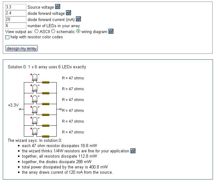
So I’ve been havin’ a bit of a poke around and came up with this, the values I entered were just from a pack of LED’s I was looking at on Ebay. Is this basically how I’d want to wire multiple LEDs to my 3.3v on the psx pad?
*edit maybe I’d be better working a battery or 3 into my stick