Just curious . . . Was there a “how to” that you used that required all those resistors?
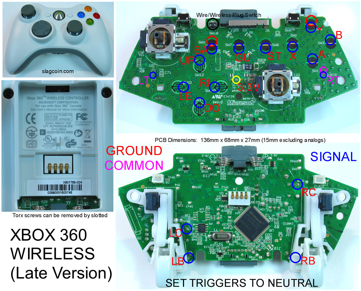
everything appears correct. you’re using 1/4 or 1/8 watt right? it’s a possibility you might have to tweak the resistors a lil. ref pic below. RayU, 4 resistors are required per analog to keep it registered as off/neutral.

It won’t have anything to do with the resistors themselves; the most likely problem is a short somewhere. Check with a multimeter to see if there is a short between the USB power (red wire) and USB ground (thin black wire) at the USB cable. If so, you need to hunt down and eliminate the short before it will work.
Meh. 2 resistors can handle all four analog axisesiisis. Do one axis as normal with the two resistors, and run a wire from the center to the center wiper points of all of the other axisesises.
thanks for the info.:tup: on all the threads i’ve read, that quickfix has never been mentioned.
I’m confused, you have the guide pic so just do it?
Yeh 1/4 watt.
I don’t have a multimeter handy at the moment but I had a look and couldn’t see any obvious signs of a short. I desoldered the resistors and tried the pad again but still nothing.
When I desoldered the analogue sticks some of the contacts came off the board but from what I can tell they still had a connection to the traces that ran to them, so I’m really out of ideas. I can post pics of my board up later on but I don’t think that will help much.
hey guys, asked this before, got no answer, as i read above 1/8 watt resistors work as well, correct?
also resistor color coding for 10k is brown-black orange, right? cause some in this thread look like brown-black-yellow which would mean 100k… and i don’t have a multi with me all the time 
I’ve only read 1/4 watt. Yeh brown-black-orange is 10k.
thanks bencao, yeah, i was aware of the codings, it’s just that the color seems a bit off on several pictures here and on the net… i was just wondering… already ordered some resistors from conrad (german shop) cause there is not one shop in town that sells resistor and even here at the job we only have 1/8 watt resistors…
thanks guys… oh, and bencao, as mentioned on hardedge i will probably go for a ms pad to make another hack, i keep having issues with my saitek… i will try again with the resistors instead of the glued down potis though.  soon to be off from work
yeah and the weekend is coming, too  Try reichelt and collect your needs. MUCH cheaper!!! And order some Flachsteckhlsen und Kabelendhlsen plus Ringelschlauch
i actually found some quick connects at the local obi was quite surprised myself. oh yeah and for all our non german friends and board users:
friday is an official day off over here
btw, just wanted to say thanks, bencao, your posts have been of great help to me, as have been the posts of many other forum members. also awesome work on your sticks! no, i will refrain from further derailing this thread
I’m trying to hack into a Wavebird right now, and it’s a lot harder doing tests than on the PC-compatible 360 controllers I’m used to.
Does anyone know how to set the triggers to digital? I can’t find a good diagram of the Wavebird circuit board, and it’s gonna be murder if for every test, I have to solder on a resistor, put the controller back together, and find a spot where the triggers should do something in a game.
I know this might’ve been asked before but I unable to search for it. I know dual wireless pcb’s are not possible but how 1 wireless and 1 wired?
I have already a modded stick with a wireless 360 pcb and I’d like to also make it a dual box so I can play on PS3 as well. Possible?
I’m hacking a dreamcast pad and I have all the wires lengthed out and attached to the strip. I was wondering though: Is it possible to solder or hot glue the wire to the “black point” on the PCB or should I try to scrape it off and then solder/hot glue? If I do decide to glue, will this affect performance/responsiveness?
I’ve done a padhack before with a MadCatz retro stick, but that PCB had little holes where I could put the wire through before soldering.
Exactly my thoughts, i refuse to work on a non common ground pcb. shitt will be too hairy balls 
sup Paxtez!
also where to get 5 volts on the xbox 360 pad?
is there a good thread or site that has a step by step for hacking a common ground wireless xbox 360 controller?
check out http://slagcoin.com/joystick/pcb_diagrams/360_diagram7.jpg
solder a wire to the areas marked in blue for signal. you can ground from any button on the pcb to chain everything on your stick. to save you time and trouble, leave the analogs & triggers alone. the solder point for RB is underneath the trigger piece, so you have to solder on the front- on the little metal point on the RB button itself.
Hello all. I hope this is the right thread; I assume I’ve made an error in building this stick, and I’m seeing a really strange issue.
I’m using a MadCatz 2009 gamepad for the PCB; specifically, this one:
http://img216.imageshack.us/img216/4827/madcatz2008sp4.jpg
I did some testing with it, and daisy-chained everything to the ground on the Up pad. In windows, everything tests fine, all buttons work, as well as they seem to all work on the XBox and in the Street Fighter 4 menus. However, once I’m actually in-game, several things don’t register anymore:
A, B, and RT do nothing (A and B work in the menus, though)
LT registers as L+M Kick, not 3K
Actually, testing in the art gallery, LT zooms in, but as soon as I let go, it zooms out (RT)
I think RT might be constantly engaged.
Here’s the method I used for the triggers:

And a few other pics of the setup:


Any ideas on how to troubleshoot/fix it? And again, I apologize if this is the wrong thread. Thanks!
i think your RT is always engaged. test this in training mode by setting RT to no function and see if A & B work. probably need to recheck resistors are soldered correctly. LT seems very odd, I didn’t have that problem. if the madcatz pad is anything like the MS one, each trigger needs it’s own ground, seperate from your daisy chain.
oh wait i just realized, resistors is the problem. look at this thread-
http://forums.shoryuken.com/showthread.php?t=169203